


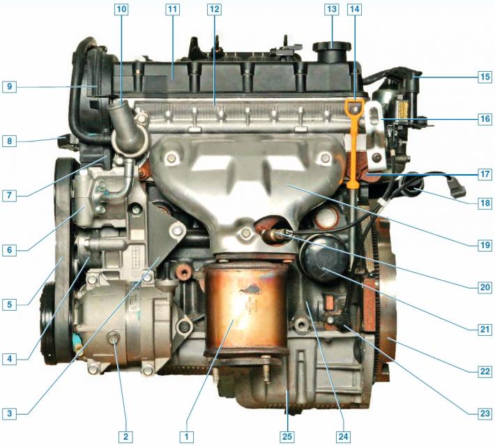
Engine (front view from the direction of the vehicle): 1 - catalytic converter of exhaust gases; 2 - air conditioning compressor; 3 — bracket for mounted units; 4 — tensioner for auxiliary drive belt; 5 — auxiliary drive belt; 6 — power steering pump; 7 — rear timing belt cover; 8 — bracket of the right support of the power unit; 9 — Upper front timing belt cover; 10 — thermostat cover; 11 — cylinder head cover; 12 — cylinder head; 13 — oil filler cap; 14 — oil level indicator (oil dipstick); 15 - ignition coil; 16 — eye; 17 — exhaust manifold; 18 — coolant pump supply pipe; 19 — heat shield of the exhaust manifold; 20 - oxygen concentration control sensor; 21 - oil filter; 22 — flywheel; 23 — crankshaft position sensor; 24 — cylinder block; 25 — oil pan.
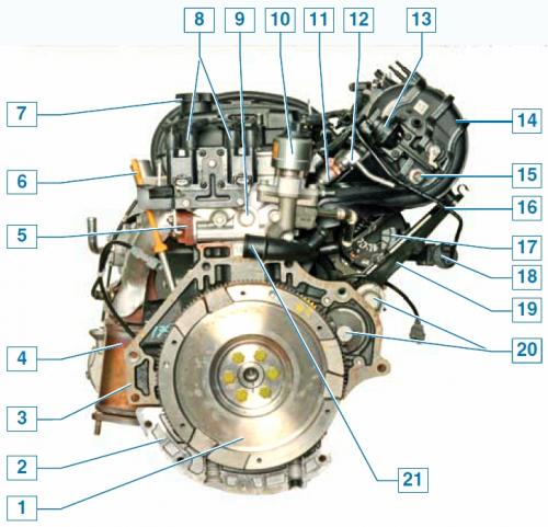
Engine (view from the left as the vehicle moves): 1 - flywheel; 2 — oil pan; 3 — cylinder block; 4 - catalytic converter of exhaust gases; 5 - exhaust manifold; 6 - oil level indicator; 7 — oil filler cap; 8 — ignition coil; 9 — cylinder head; 10 — exhaust gas recirculation valve; 11 — nozzle; 12 — fuel rail; 13 — actuator of the intake tract length change system; 14 — intake manifold; 15 - intake air temperature sensor; 16 — fuel vapor supply pipe from the adsorber purge valve to the intake manifold; 17 — generator; 18 — purge valve of the adsorber; 19 — intake manifold bracket; 20 — starter; 21 — coolant pump supply pipe.
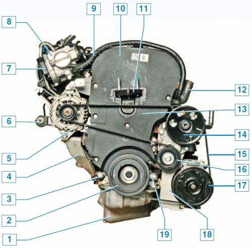
Engine (view from the right as the vehicle moves): 1 — oil pan; 2 — auxiliary drive pulley; 3 - oil pressure sensor; 4 — generator bracket; 5 - generator; 6 — purge valve of the adsorber; 7 — throttle position sensor and idle speed control unit; 8 — throttle assembly; 9 — coolant supply hose to the throttle assembly; 10 - Upper front timing belt cover; 11 — cylinder block bracket for fastening the right support of the power unit; 12 — thermostat cover; 13 - lower front timing belt cover; 14 — power steering pump pulley; 15 — auxiliary drive belt; 16 — roller of automatic tensioner of auxiliary drive belt; 17 — air conditioning compressor pulley; 18 — auxiliary units bracket; 19 — oil pump.
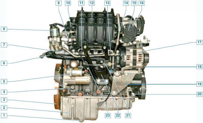
Engine (rear view from the direction of the vehicle): 1 - oil drain plug; 2 — oil pan; 3 — flywheel; 4 — cylinder block; 5 — starter; 6 — coolant pump supply pipe; 7 — cylinder head; 8 — exhaust gas recirculation valve; 9 — fuel rail; 10 — actuator for changing the length of the intake tract; 11 — coolant supply pipe to the heater radiator; 12 — inlet manifold; 13 - coolant temperature sensor; 14 — exhaust gas supply pipe to the intake manifold; 15 — throttle position sensor and idle speed control unit; 16 — throttle assembly; 17 — generator; 18 — auxiliary drive belt; 19 — generator bracket; 20 - Low oil pressure sensor; 21 — purge valve of the adsorber; 22 — intake manifold bracket; 23 — knock sensor.
The engine is gasoline, four-stroke, four-cylinder, in-line, sixteen-valve, with an overhead arrangement of two camshafts. The arrangement in the engine compartment is transverse. The order of cylinder firing: 1–3–4–2, counting from the auxiliary drive pulley. The fuel system is phased distributed fuel injection.
The engine with the gearbox and clutch form a power unit - a single block, fixed in the engine compartment on three elastic rubber-metal supports. The right support is attached to the cylinder block through a bracket, and the left and rear ones - to the gearbox housing.
On the right side of the engine (in the direction of the vehicle's movement) located: timing drive and coolant pump (toothed belt); drive of auxiliary units - generator, air conditioning compressor and power steering pump (poly V-belt with automatic tensioner); oil pump.
On the left are the ignition coils and the exhaust gas recirculation valve.
Front: Exhaust manifold; catalytic converter of exhaust gases; oil filter; oil level indicator; crankshaft position sensor; power steering pump (top right); air conditioning compressor (bottom right).
Rear: intake manifold with throttle assembly, absolute pressure and intake air temperature sensors, intake tract length adjustment mechanism, fuel rail with injectors; generator (top right); starter (bottom left), low oil pressure sensor; purge valve of the adsorber; knock sensor; coolant pump inlet pipe; coolant temperature gauge sensor.
Top: spark plugs, phase sensor.
The cylinder block is cast iron, the cylinders are bored directly in the block. The engine cooling jacket and oil channels are made in the body of the cylinder block.
At the bottom of the cylinder block there are five main bearing supports of the crankshaft with removable covers, which are attached to the block with special bolts. The holes in the cylinder block for the bearings are processed with the covers installed, therefore the covers are not interchangeable and are marked on the outer surface with numbers (timing pulley count).
The crankshaft is made of high-strength cast iron, with five main journals and four connecting rod journals.
The shaft is equipped with eight counterweights, cast together with it. The liners of the main and connecting rod bearings of the crankshaft are steel, thin-walled, with an antifriction coating.
The main and connecting rod journals of the crankshaft connect the channels located in the shaft body. The axial movement of the crankshaft is limited by two liners with thrust flanges of the third main bearing.
At the front end (nose) of the crankshaft are installed: a toothed pulley for the timing mechanism (GRM) drive and a pulley for the auxiliary units drive.
The flywheel is attached to the crankshaft flange with six bolts. It is cast iron and has a pressed-on steel toothed ring for starting the engine with a starter.
The connecting rods are forged steel, I-section. With their lower (detachable) the connecting rod heads are connected through liners to the connecting rod journals of the crankshaft, and the upper heads are connected to the pistons using piston pins.
The pistons are made of aluminum alloy. The hole for the piston pin is offset relative to the axis of symmetry of the piston by a small amount toward the rear wall of the cylinder block. Three grooves for piston rings are machined in the upper part of the piston. The two upper piston rings are compression rings, and the lower one is an oil scraper compound (two disks and an expander). Piston pins are steel, tubular section.
The pins are installed with a gap in the piston holes and with tension in the upper heads of the connecting rods (pressed in).
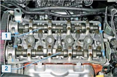
Cylinder head assembly: 1 - intake camshaft; 2 — exhaust camshaft.
The cylinder head is cast from an aluminum alloy and is common to all four cylinders.
The head is centered on the block with two bushings and secured with ten bolts. A sealing gasket is installed between the block and the cylinder head. The intake and exhaust ports are located on opposite sides of the cylinder head. Spark plugs are installed in the center of each combustion chamber.
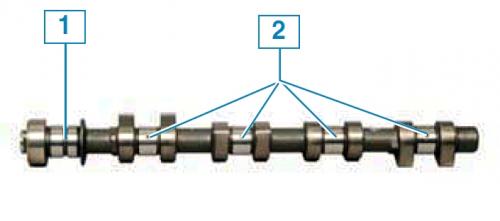
Camshaft: 1 - groove and hole for supplying oil inside the shaft; 2 - holes for supplying oil to the bearings.
Two camshafts made of cast iron are installed in the upper part of the cylinder head. One shaft drives the intake valves of the valve timing mechanism, and the other drives the exhaust valves. Eight cams are made on the shaft - an adjacent pair of cams simultaneously controls two valves (inlet or outlet) each cylinder. Supports (bearings) camshafts (five supports for each shaft) are made detachable. The holes in the supports are processed together with the covers.
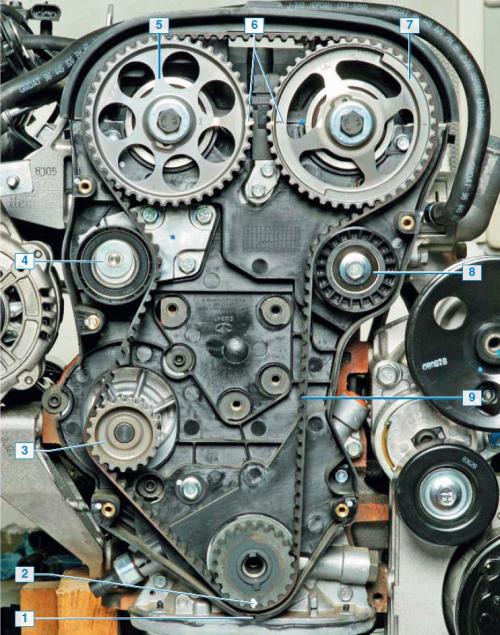
Timing drive: 1 - mark on the rear timing belt cover; 2 - mark on the toothed pulley of the crankshaft; 3 - coolant pump pulley; 4 — belt tensioner roller; 5 — intake camshaft pulley; 6 - marks on the camshaft pulleys; 7 — exhaust camshaft pulley; 8 — belt support roller; 9 — belt.
The camshaft drive is a toothed belt from the crankshaft pulley. A semi-automatic tensioner ensures the required belt tension during operation.
The valves in the cylinder head are arranged in two rows, V-shaped, with two inlet and two outlet valves per cylinder. The valves are made of steel, the outlet valves have a heat-resistant steel plate and a welded chamfer.
The diameter of the inlet valve plate is larger than the outlet valve. The valve seats and guide bushings are pressed into the cylinder head. The valve guide bushings are topped with oil-deflecting caps made of oil-resistant rubber.
The valve is closed by a single spring. Its lower end rests on a washer, and its upper end rests on a plate held by two crackers. The crackers, when folded together, have the shape of a truncated cone, and their inner surface has flanges that fit into grooves on the valve stem.
The valves are actuated by camshaft cams via hydraulic tappets.
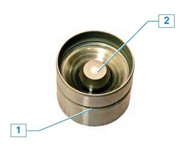
Hydraulic tappet: 1 - groove for oil supply; 2 - plunger pair.
To operate the hydraulic tappets, the cylinder head has channels that supply engine oil to them. When the engine is running, the oil under pressure fills the internal cavity of the hydraulic tappet and moves its plunger pair, compensating for the thermal clearance in the valve drive. Thus, constant contact is ensured between the tappet and the camshaft cam.
Engine lubrication is combined. Under pressure, oil is supplied to the main and connecting rod bearings of the crankshaft, the bearing-to-camshaft journal pairs and hydraulic tappets.
The pressure in the system is created by an oil pump with internal gears and a pressure reducing valve. The oil pump is attached to the cylinder block on the right.
The pump's drive gear is mounted on the crankshaft nose. The pump takes oil from the oil pan via the oil receiver and supplies it through the oil filter to the main oil line of the cylinder block, from which the oil channels to the crankshaft main bearings and the oil supply channel to the cylinder head branch off.
To lubricate the camshaft bearings, oil is supplied to the first through channels in the cylinder head (from the timing drive side) shaft supports.
Through the groove and drilling made on the first journal, oil gets inside the shaft and then through the drillings in the journals to the other bearings of the shaft.
The oil filter is full-flow, non-separable, equipped with bypass and anti-drain valves. Splashing oil is supplied to the pistons, cylinder walls and camshaft cams. Excess oil flows through the cylinder head channels into the oil pan.
Hydraulic tappets are very sensitive to the quality of oil and its purity. If there are mechanical impurities in the oil, the plunger pair of the hydraulic tappet may quickly fail, which is accompanied by increased noise in the valve timing mechanism and intensive wear of the shaft cams. A faulty hydraulic tappet cannot be repaired - it must be replaced.
The crankcase ventilation system is forced, closed type.
Through the channels in the cylinder head, gases from the engine crankcase enter under the cylinder head cover. After passing through the oil separator (located in the cylinder head cover), the gases are cleaned from oil particles and, under the action of vacuum, enter the engine intake tract through the hoses of two circuits: the main circuit and the idle circuit, and then into the cylinders. Through the main circuit hose, the crankcase gases are supplied to the throttle assembly in partial and full engine load modes.
Through the idle circuit hose, gases are discharged into the space behind the throttle valve, both in partial and full load modes and in idle mode. The engine management, fuel supply, cooling and exhaust systems are described in the relevant chapters.
[For details, visit the website: «ChevyMan»]