ChevyMan.ru
Mazda Mitsubishi Toyota Land Rover Honda Kia Nissan
English Русский
Български
Беларускі
Український
Српски
Hrvatski
Română
Polski
Slovenský
Magyar
|
Articles | Sitemap | Contacts |


Home   Aveo   Captiva   Cruze   Lacetti   Lanos   Niva   Tahoe   Others  
Lacetti 1 (2002-2009)
  • Home
  • Lacetti
  • J200 (2002-2009)
  • Power unit
  • Engine repair
  • Replacing the powertrain mounts

Replacing the powertrain mounts (Chevrolet Lacetti J200)

            0

Contents: Replacing the left engine mount ↧ Replacing the right engine mount ↧ Replacing the rear engine mount ↧
We replace the support if the rubber breaks or peels off from the metal parts of the support, which can cause knocking when starting the engine and when driving over uneven surfaces.

Replacing the left engine mount


Disconnect the wire terminal from the negative terminal of the battery. Disconnect the wiring harness connector from the electronic engine control unit (see Removal the electronic control unit).
Disconnect the wire terminal from the negative terminal of the battery. Disconnect the wiring…


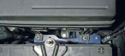
Using a 10 mm socket, unscrew the two nuts on the front mounting cover of the fuse and relay mounting block in the engine compartment.
Using a 10 mm socket, unscrew the two nuts on the front mounting cover of the fuse and relay…


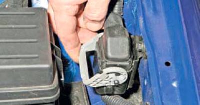
Lifting the latch…

Lifting the latch…


…we disconnect the wiring harness blocks secured to the bracket near the left wing, next to the mounting block.
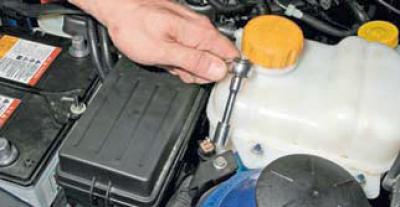


…we disconnect the wiring harness blocks secured to the bracket near the left wing, next to the…


Using a 10 mm socket, unscrew the bolt securing the ABS diagnostic connector bracket and move the bracket with the connector to the side.

We remove the wiring harness of the engine control unit from the fuse and relay mounting block.
We remove the wiring harness of the engine control unit from the fuse and relay mounting block.


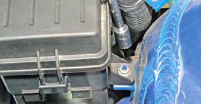
Using a 10 mm head, unscrew the nut of the rear mounting of the mounting block casing, and after removing the mounting block casing from the studs, move the block assembly away (without disconnecting the wiring harness pads from it) away from the left support of the power unit.
Using a 10 mm head, unscrew the nut of the rear mounting of the mounting block casing, and after…


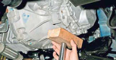
We install an adjustable stop under the gearbox.


We install an adjustable stop under the gearbox.


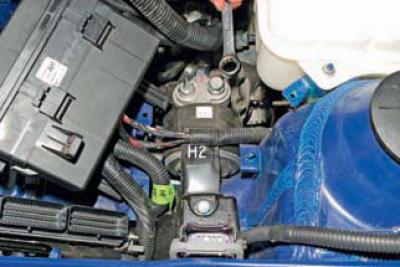
Using a spanner or a 19 mm socket, unscrew the nut and bolt securing the adapter to the support bracket.
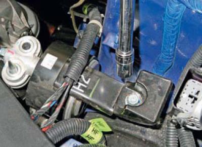
Using a spanner or a 19 mm socket, unscrew the nut and bolt securing the adapter to the support…


Using a 14 mm head with an extension, unscrew the upper bolt…
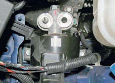
Using a 14 mm head with an extension, unscrew the upper bolt…


…and two bolts for the lower mounting of the support to the body.
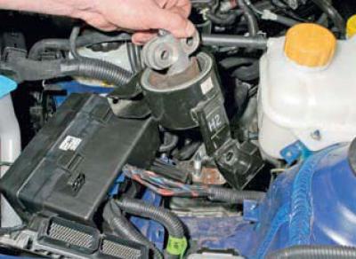
…and two bolts for the lower mounting of the support to the body.


We remove the support assembly with the adapter from the support bracket pin and remove it from the engine compartment.


We remove the support assembly with the adapter from the support bracket pin and remove it from the…


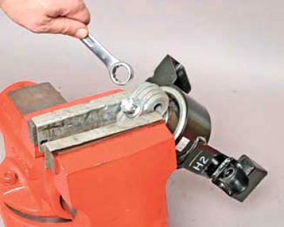
Having clamped the support adapter in a vice with soft metal jaw pads, we unscrew the bolt holding it in place using a 17 mm open-end wrench…
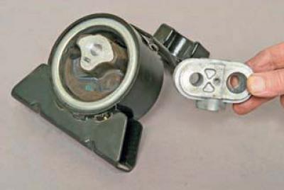
Having clamped the support adapter in a vice with soft metal jaw pads, we unscrew the bolt holding…


…and remove the adapter.

…and remove the adapter.


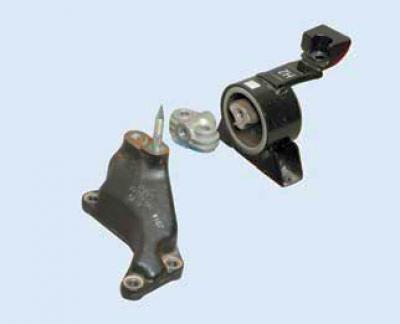
Fastening elements of the left support of the power unit to the gearbox: support bracket; adapter; support.

We assemble and install the left support of the power unit in the reverse order. We tighten the support mounting bolts to the prescribed torques (see Tightening torques for critical threaded connections).


Replacing the right engine mount


Remove the air filter (see Removal the air filter).
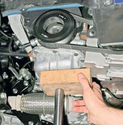
Remove the air filter (see Removal the air filter).


We place an adjustable stop under the engine oil pan.
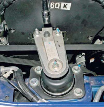
We place an adjustable stop under the engine oil pan.


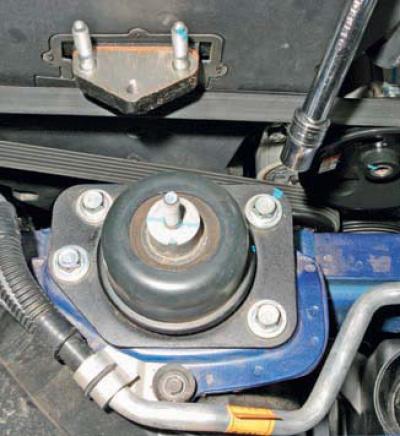
Using a 14 mm head, unscrew the two nuts and the bolt securing the support bracket to the cylinder block bracket, as well as the nut securing the support bracket to the support stud.
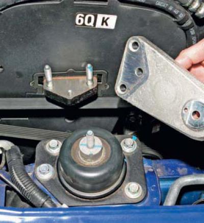
Using a 14 mm head, unscrew the two nuts and the bolt securing the support bracket to the cylinder…


We remove the support bracket.


We remove the support bracket.


Using a 14 mm socket head, unscrew the four bolts securing the support to the body…
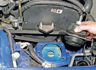
Using a 14 mm socket head, unscrew the four bolts securing the support to the body…


…and remove the right support of the power unit.

We install the right support of the power unit in the reverse order.
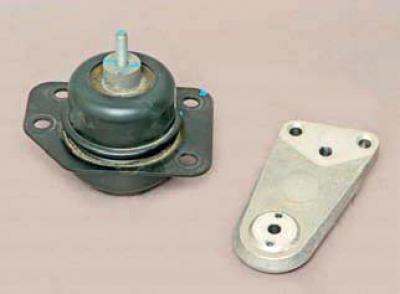
We install the right support of the power unit in the reverse order.


When installing the bracket, the protrusions on the support flange must enter the holes in the bracket.

Tighten the bolts and nuts securing the support and support bracket to the specified torques (see Tightening torques for critical threaded connections).

Replacing the rear engine mount
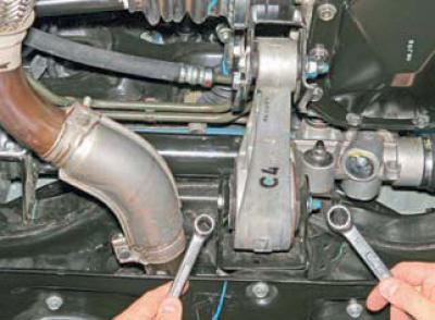


Replacing the rear engine mount


Using a 17 mm open-end wrench, unscrew the nut of the bolt securing the rear support to the front suspension subframe, holding the bolt from turning with a 14 mm open-end wrench. Similarly, unscrew the nut of the bolt securing the support to the gearbox bracket.

We remove the bolt securing the support to the gearbox bracket.
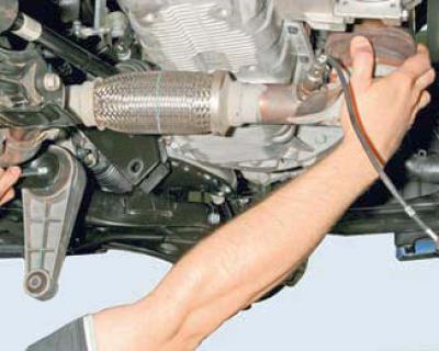
We remove the bolt securing the support to the gearbox bracket.


Having moved the engine back so that the intermediate pipe does not interfere, we remove the bolt securing the support to the subframe…
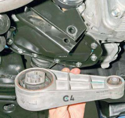
Having moved the engine back so that the intermediate pipe does not interfere, we remove the bolt…


…and remove the rear support.

We install the rear support in the reverse order.

At the same time…
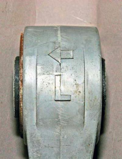
At the same time…


…the arrow on the support body should be located at the bottom and directed towards the left side of the vehicle.

Tighten the nuts of the support mounting bolts to the prescribed torques (see Tightening torques for critical threaded connections).

The original material is located on the website «chevyman»

The article was checked: Vladimir Romannikov
This article is available at russian, bulgarian, belarusian, ukrainian, serbian, croatian, romanian, polish, slovak, hungarian

Share information:

Previous articles
Lacetti 1: Engine repair
Next articles

Removal the low oil pressure sensor
Replacing the rear crankshaft oil seal
Replacing the front crankshaft oil seal
Removal camshafts and hydraulic valve lifters
Replacing the cylinder head cover gasket
Removal and installation the engine
Replacing the auxiliary drive belt tensioner roller


See similar articles on the topic of Chevrolet cars:
Replacing the left support of the powertrain suspension Chevrolet Aveo T300 (2012-2018)
Replacing windshield wiper blades Chevrolet Captiva 1 (2006-2018)
Replacing the powertrain suspension mounts Chevrolet Cruze 1 (2008-2016)
Replacing Windshield Wiper Blades Chevrolet Lanos T150 (2002-2009)
Replacing fuses Chevrolet Niva 1 (2002-2016)
Transmission Mounts — Checking and Replacing Chevrolet Tahoe 1 (1992-2000)
Checking and replacing engine mounts Chevrolet Lumina 1 (1989-1994)
Link in different formats to this page


Visitor comments

No comments yet


How much will 32 + 24 =


Lacetti 1 (2002-2009) 
  • General information
  • User manual
  • Maintenance
  • Power unit
  • Engine repair
  • Control system
  • Supply system
  • Cooling system
  • Exhaust system
  • Transmission
  • Clutch
  • Manual gearbox
  • Front wheel drives
  • Chassis
  • Front suspension
  • Rear suspension
  • Steering
  • Brake system
  • Body
  • Repair of body elements
  • Heating and air conditioning
  • Electrical equipment
  • Engine electrics
  • Lighting and lamps
  • Equipment and devices
  • Electrical circuits


ChevyMan.ru © 2017-2026 · Mobile version · Feedback · Site search · Interesting to read · Sitemap: EN BG BY UA RS HR RO PL SK HU

Aveo 2003-2008 · Aveo 2006-2011 · Aveo 2012-2018 · Captiva 2006-2018 · Cruze 2008-2016 · Lacetti 2002-2009 · Lanos 2002-2009 · Niva 2002-2016 · Tahoe 1992-2000 · Tahoe 2000-2014 · Lumina 1 1989-1994 · Trailblazer 1 2001-2008 · Orlando 1 2010-2018 ·
🛡️ For your security and to improve our service, this site uses cookies. You can disable them in your browser.