


Note: The intake manifold consists of an upper and lower section. Removal of the upper intake manifold is required for only some jobs (eg fuel injector/spark plug service), while some other jobs require removal of both the upper and lower sections as a unit (for example, cylinder head maintenance). If you need to remove only the upper manifold, see section "Upper intake manifold" in this section.
Removal procedure
1. Relieve pressure in the fuel system. See Section 1F3, Engine Controls - HFV6 3.2L.
2. Disconnect the negative battery cable.
3. Remove the air intake duct.
4. Remove the decorative engine cover. See "Decorative Engine Cover" in this section.

Caution: When disconnecting the throttle body wiring harness, the following precautions must be taken.
- Do not use any mechanical tools such as a screwdriver to disconnect the harness connector (1) from the throttle body (2).
- When removing the lock (3) of the throttle body wiring connector, be careful not to disconnect it from the connector.
- Do not pull on the connector wires.
5. Remove the lock (3) from the throttle body wiring connector.
6. While pressing the connector lock in the direction indicated by the arrow (4), disconnect the throttle body wiring connector.
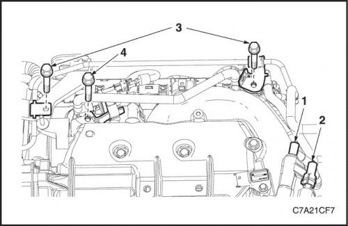
7. Disconnect the positive crankcase ventilation hose (1) and the vacuum hose (2) for purging the EGR canister.
8. Remove the bolts (3) securing the pipe bracket between the expansion tank and the water outlet.
9. Remove the bolt (4) securing the bracket of the purge valve of the SUPB adsorber.
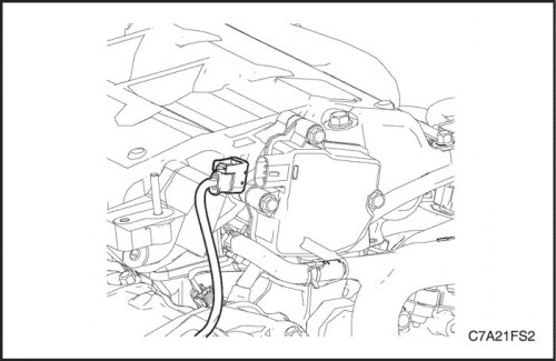
10. Disconnect the wiring harness connector from the Intake Manifold Tuning (IMTC) valve.
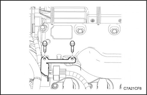
11. Remove the engine wiring harness connector mounting bracket.
12. Move all parts located near the upper intake manifold away from it.
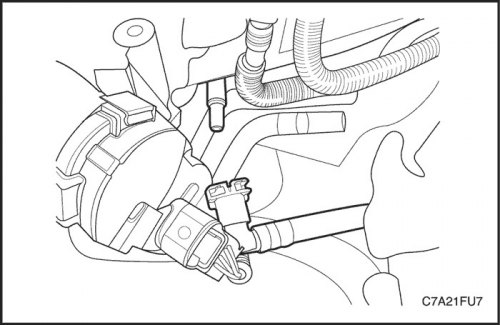
Caution: Seal the fuel supply hose opening after removal to prevent dirt and other substances from entering the fuel system.
13. Disconnect the fuel line from the fuel rail.
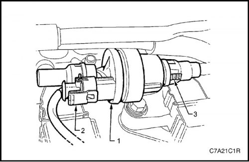
14. Disconnect the wiring harness connector (2) from the EGR valve (1).
15. Disconnect the quick-release coupling (3) at the rear of the EGR valve, proceeding in the following sequence:
- a. Press the two ribbed tabs together, push the quick release coupling towards the valve, and then pull it back to release.
- b. Seal both open ends to prevent foreign material from entering.
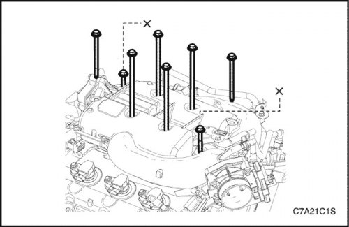
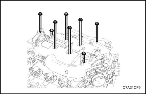
16. Remove the four long (1) bolts securing the intake manifold assembly to the cylinder heads.
Caution: Do not loosen or remove the shortest bolts (X) that connect the upper and lower intake manifolds.
17. Remove the two short (2) bolts securing the lower intake manifold to the cylinder heads.
Caution: After removing the intake manifold, plug each of the cylinder head intake ports with a lint-free cloth to prevent foreign material from entering.
18. Remove the upper and lower intake manifolds as an assembly from the engine.
19. Remove the gasket between the lower intake manifold and the cylinder heads.
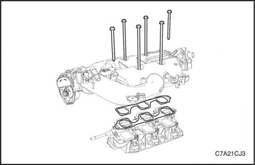
20. Remove the bolts securing the upper intake manifold to the lower one.
21. Remove the upper intake manifold from the lower one.
Caution: Do not reuse the gaskets located between the upper and lower intake manifolds.
22. Remove and discard the gaskets located between the upper and lower intake manifolds.
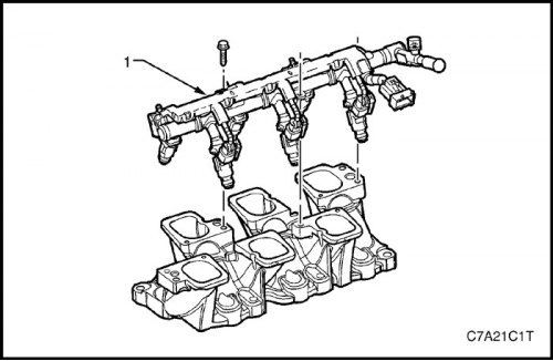
Caution! When removing the fuel rail and injectors assembly (1), the following precautions must be observed:
- a. It is necessary to ensure that when removing the fuel rail with the injectors as an assembly, the spray tips of the injectors and the contacts of the wiring harness connector are not damaged.
- b. After removal, it is necessary to place the fuel rail with injectors assembled on the support.
- c. Plug all fuel lines and manifold openings after removal to prevent dirt and other substances from entering the fuel system.
23. Remove the fuel rail and injectors as an assembly if required. See Section 1F3, Engine Controls - HFV6 3.2L.
Clear
Caution! Since the intake manifold is made of aluminum alloy, do not use wire brushes or steel scrapers to clean it, as this may damage the sealing surfaces. It is preferable to use wooden or plastic scrapers.
1. Clean the mating surfaces, removing all gasket residue.
2. Clean the manifold with a suitable solvent.
3. Dry the valve timing components with compressed air.
Inspection
1. Inspect the intake manifold for the following faults:
- Damaged sealing or mating surfaces.
- Damaged lower intake manifold gasket.
- Damage or excessive contamination of threaded and through holes.
- Cracks or damage to the intake manifold housing.
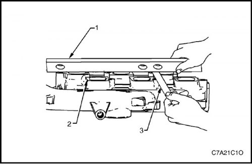
2. Place a straight edge (1) across the sealing surface (2) of the upper intake manifold.
3. Using the feeler gauge (3), measure the gap between the manifold and the ruler.
4. If the gap between the sealing surface of the upper manifold and the ruler exceeds the specified maximum warpage, replace the manifold.
- Maximum warpage of the upper manifold: 0.05 mm
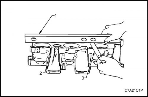
5. Place a straight edge (1) across the sealing surface (2) of the lower intake manifold.
6. Using the feeler gauge (3), measure the gap between the manifold and the ruler.
7. If the gap between the sealing surface of the lower manifold and the ruler exceeds the specified maximum warpage, replace the manifold.
- Maximum warpage of the lower manifold: 0.05 mm
Installation procedure
1. Install the fuel rail and injectors as an assembly, if required. See Part 1F3, Engine Mechanical - HFV6 3.2L.
2. Install the lower intake manifold onto the cylinder head.
Tighten
Tighten the lower intake manifold to cylinder head bolts to 23 N·m (17 lb-ft).
3. Install the upper intake manifold onto the lower one and onto the cylinder head.
Tighten
Tighten the lower intake manifold to lower intake manifold mounting bolts to 23 N·m (17 lb-ft).
Tighten the upper intake manifold to cylinder head bolts to 23 N·m (17 lb-ft).
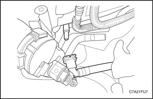
4. Connect the fuel injector connector.
5. Connect the fuel supply line to the fuel rail.
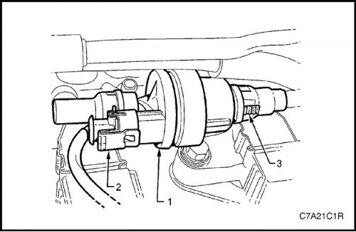
6. Connect the Evaporative Coolant Bleed Valve connector and quick-release coupling.
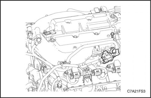
7. Connect the IMTC connector.
8. Connect the throttle valve connector.
9. Install the bolt for fixing the bracket of the purge valve of the SUPB adsorber.
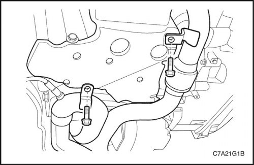
10. Install the pipe bracket mounting bolts between the expansion tank and the water outlet.
11. Connect the ECU vacuum hose and the positive crankcase ventilation hose to the upper intake manifold.
(Original version of the article on the website ChevyMan.ru)