


Contents: Removal and installation the… ↧ Removal and installation the valve ↧ Variable valve timing system drive… ↧
This system has been installed on models since 2007.
Removal and installation the electromagnetic valve
1. Remove the coolant pump.
2. Disconnect the connector from the variable valve timing solenoid valve.
3. Unscrew the bolts (751) securing the valve (752), remove it. Tightening torque 12 Nm.
4. Remove and discard the gasket (753).
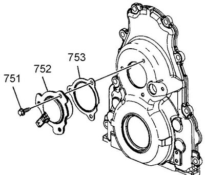
5. Installation is carried out in reverse order.
Removal and installation the valve
1. Remove the variable valve timing solenoid valve.
2. Remove the system valve.
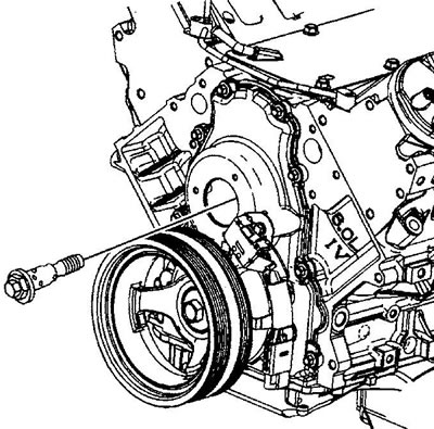
3. Install the variable valve timing system valve. Tighten the valve. Tightening torque: 1st pass by hand; 2nd pass 65 Nm; Turn the 3rd pass 90°.
4. Install the variable valve timing solenoid valve.
Variable valve timing system drive clutch
Removal
1. Remove the oil pump.
2. Remove the valve (234) of the variable valve timing system.
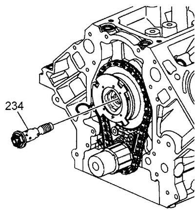
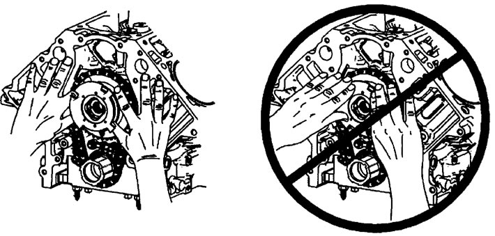
Caution: When removing and installing the drive coupling, do not apply axial force to the synchronizing ring of the camshaft position sensor. The synchronizing ring is attached to the drive coupling of the variable valve timing system with three pins, so applying axial force may cause the ring to shift and the return spring of the drive to unwind the ring, causing injury.
3. Loosen the bolt and remove the drive coupling and timing chain from the camshaft nose. Place your fingers under the drive coupling sprocket and pull the drive off.
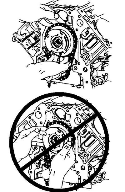
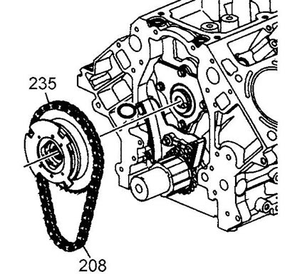
Removing the variable valve timing system drive clutch
4. Remove the drive (235) and chain (208).
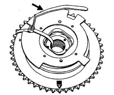
5. Use a plastic clamp or wire to secure the camshaft position sensor synchronizing ring to the variable valve timing system drive coupling.
Installation
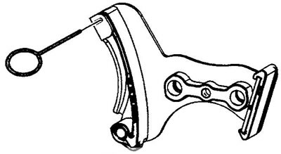
1. Compress the chain tensioner and secure it with a suitable pin.
Attention:
- Correctly orient the variable valve timing system coupling relative to the installation pin.
- The sprocket teeth and chain links must engage.
- Align the timing marks on the camshaft and crankshaft sprockets.
- NEVER re-install the removed solenoid valve on the valve timing system drive coupling.
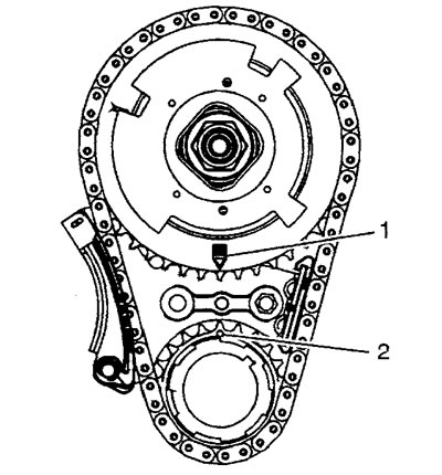
2. Determine the relative position of the mounting hole (1) on the camshaft drive sprocket and the mounting pin (2).
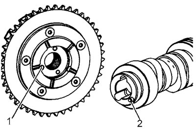
3. Install the drive coupling together with the chain on the camshaft nose using the installation pin. If necessary to align the marks on the camshaft and crankshaft sprockets, slightly turn one or both shafts in the desired direction. Push the drive onto the shaft by the sprocket, never push the drive coupling by the synchronizing ring.
Installing the variable valve timing system drive clutch
Caution: When removing and installing the drive coupling, do not apply axial force to the synchronizing ring of the camshaft position sensor. The synchronizing ring is attached to the drive coupling with three pins, so applying axial force may cause the ring to shift and the return spring of the drive to unwind the ring, causing injury.
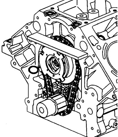
4. Apply a ruler to the front surface of the cylinder block and check the correct installation of the drive and chain: when installed correctly, the chain should not protrude beyond the plane of the front surface of the block.
5. Install the variable valve timing system valve. Tighten the valve by hand.
6. Check the alignment of timing marks (1) and (2). The mark on the camshaft sprocket should be at the 6 o'clock position, and on the crankshaft sprocket - at the 12 o'clock position.
7. Remove the chain tensioner guide retaining pin.
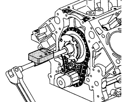
8. Tighten the variable valve timing actuator valve. Tightening torque: 1st pass 65 Nm; 2nd pass turn 90°.
9. Install the oil pump.