
Contents: Removal ↧ Installation ↧
Removal
1. Left half-block head: remove the generator bracket. Right half-block head: remove the oil dipstick guide.
2. Remove the intake manifold.
3. Remove the air bleed tube from the cooling system.
4. Remove the exhaust manifold of the left and/or right half-block.
5. Remove the push rods.
6. If installed: Loosen the ground busbar mounting bolt at the rear of the left half-block head or at the front of the right half-block.
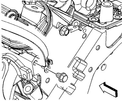
Left half block tire |
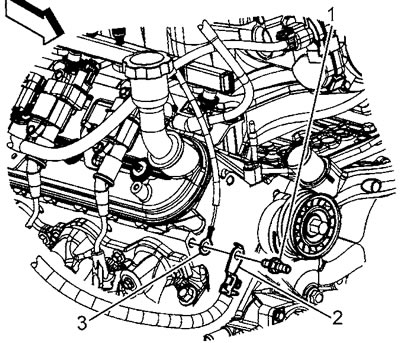
Right half-block bus. 1 - bolt, 2 - battery cable, 3 - ground bus |
7. If installed: Separate the ground bus from the cylinder head.
8. Unscrew the cylinder head mounting bolts. Discard the bolts; reinstallation of the bolts is not permitted.
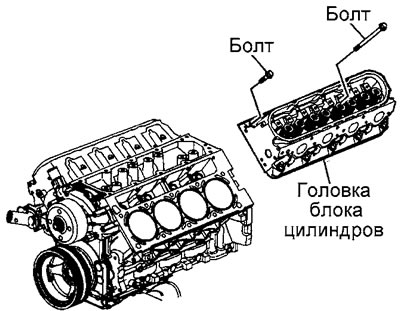
Late model engine cylinder head mounting bolts |
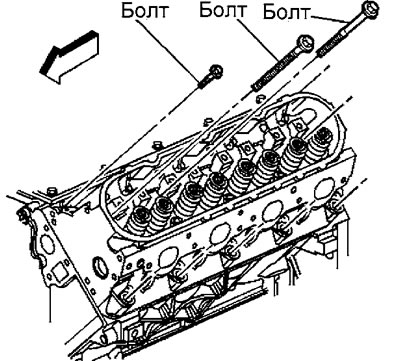
Early model engine cylinder head mounting bolts |
9. Remove the cylinder head and discard the head gasket.
Installation
Caution: Before installation, clean the mating surfaces of the cylinder head and block. The threaded holes for the head mounting bolts in the block must be clean and dry. Lubricating the gasket or applying sealant to it is prohibited.
1. If necessary, clean the threaded holes with a tap.
2. Clean the threaded holes with solvent.
3. Dry the threaded holes with compressed air.
Warning: Wear safety glasses.
4. Check the protrusion "a" of the guide pins.
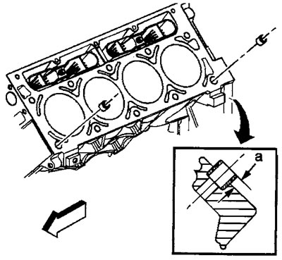
Protrusion "a" = 6 mm
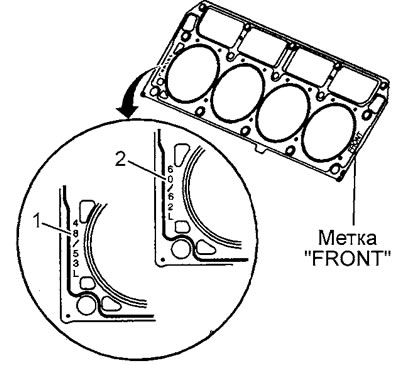
5. Install a NEW cylinder head gasket.
Attention:
- Left Cylinder Head: When the gasket is installed correctly, the FRONT mark should be on the left and the protrusion on the bottom of the gasket should be to the left of center.
- Right half block head: When the gasket is installed correctly, the FRONT mark should be on the right and the protrusion on the bottom of the gasket should be to the right of center.
- The gasket must be of a certain thickness, see identification marks on the gasket.
6. Install the cylinder head onto the guide pins.
7. The holes in the block for the cylinder head mounting bolts have two design options: with short and long threads (first design) and only with short thread (2nd design).
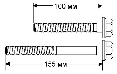
Before installing the bolts, measure the depth of the threaded holes.
8. Install NEW cylinder head bolts.
9. Tighten the cylinder head bolts in the sequence shown in the accompanying illustration, see illustration on the next page.
Tightening torque:
- First design:
- bolts M11 (1-10) 1st pass 30 Nm
- bolts M11 (1-10) 2nd pass turn 90°
- bolts M11 (1-8) 3rd pass turn 90°
- bolts M11 (9 and 10) 3rd pass tighten by 50°
- bolts M8(11-15) 30 Nm
- Second design:
- bolts M11 (1-10) 1st pass 30 Nm
- bolts M11 (1-10) 2nd pass turn 90°
- bolts M11 (1-10) 3rd pass tighten by 70°
- bolts M8 (11-15) 30 Nm
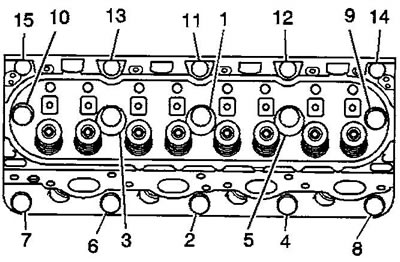
To point 9, the sequence of tightening the cylinder head bolts
10. If installed: install the ground busbar at the rear of the left half-block head or at the front of the right half-block head. Tighten the mounting bolt. Tightening torque 16 Nm.
11. Install the push rods.
12. Install the exhaust manifold of the left half-block.
13. Install the cooling system air bleed tube.
14. Install the intake manifold.
15. Install the generator bracket and/or dipstick guide.