


Removal procedure
Cylinder bank 1
1. Remove the cylinder head cover of cylinder bank 1. See "Cylinder head cover" in this section.
2. Remove the camshaft timing actuators for cylinder bank 1. See "Valve timing drive assembly" in this section.
3. Remove tool EN 46105-1 (1) from camshafts (2) of cylinder bank 1.
Note: The EN-46105 tool was installed during the operations to remove the camshaft timing actuators for cylinder bank 1.
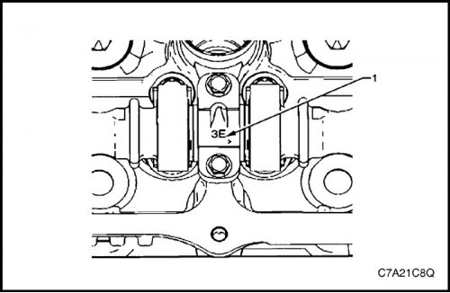
4. It is necessary to pay attention to the marking (1) on the bearing caps. Each bearing cap has a marking that determines its location. This marking contains the following information:
- The raised area should always be oriented towards the center of the cylinder head.
- The letter I stands for intake camshaft.
- The letter E stands for exhaust camshaft.
- The number indicates the journal number of the shaft, counting from the front of the engine.
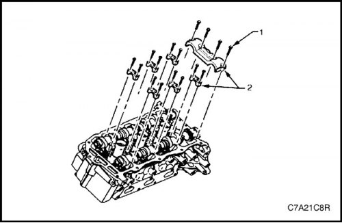
5. Remove the screws (1) of the camshaft bearing caps and the caps (2).
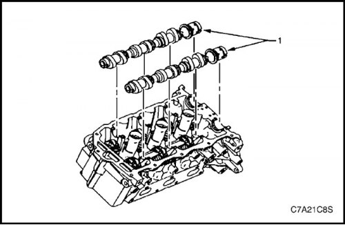
6. Remove the camshafts (1).
7. Wash the camshaft in solvent and dry with compressed air.
Cylinder bank 2
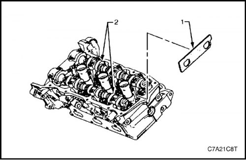
1. Remove the camshaft timing actuators for cylinder bank 2. See "Valve timing drive assembly" in this section.
2. Remove tool EN-46105 - 1 (1) from bank 2 camshafts.
Note: The EN-46105 tool was installed during the operations to remove the camshaft timing actuators for bank 2.
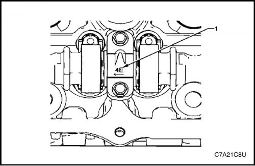
3. It is necessary to pay attention to the marking (1) on the bearing caps. Each bearing cap has a marking that determines its location. This marking contains the following information:
- The raised area should always be oriented towards the center of the cylinder head.
- The letter I stands for intake camshaft.
- The letter E stands for exhaust camshaft.
- The number indicates the journal number of the shaft, counting from the front of the engine.
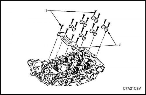
4. Remove the screws (1) of the camshaft bearing caps and the caps (2).
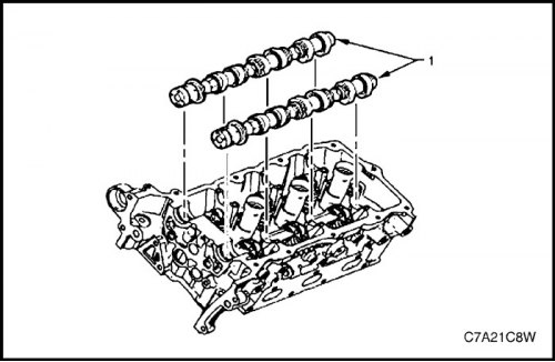
5. Remove the camshafts (1).
6. Wash the camshaft in solvent and dry with compressed air.
Inspection
Inspection of the camshaft
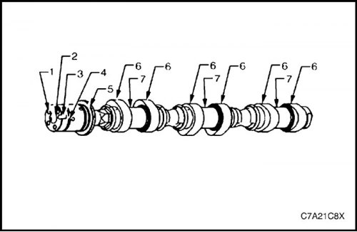
1. Inspect the oil supply holes (1) to the variable valve timing drive for dirt or blockage.
2. Inspect the threaded hole (2) for damage.
3. Inspect the installation groove (3) for the variable valve timing drive for damage or wear.
4. Inspect the sealing grooves (4) of the camshaft for damage.
5. Inspect the thrust surface (5) of the camshaft for damage, dirt or clogging.
6. Inspect the camshaft cams (6) and journals (7), checking for the following faults:
- Too many scratches or chipping
- Color change due to overheating
- Deformation due to excessive wear, especially of the camshaft lobes
7. If the camshaft has any of the listed faults, the shaft should be replaced.
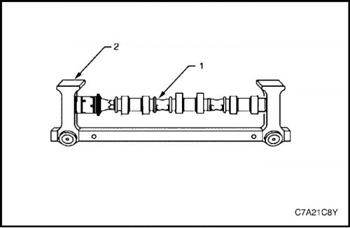
Camshaft Measurements
1. After installing the camshaft (1) in the appropriate fixture (2), take measurements to determine wear.
Caution! Any mechanical treatment of the camshaft is not permitted.
Note: If the camshaft measurement results are outside the required value range, the shaft must be replaced.
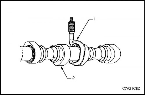
2. Measure the diameter and out-of-roundness of the camshaft journal (2) using a micrometer (1).
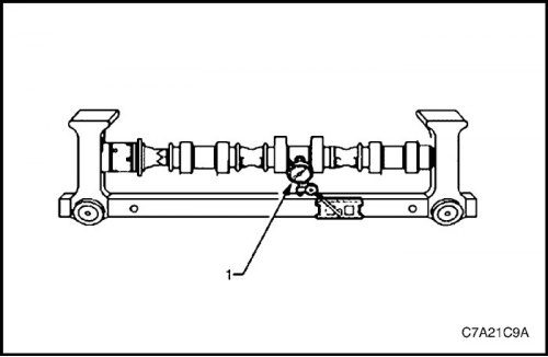
3. Measure the camshaft runout using a dial indicator (1).
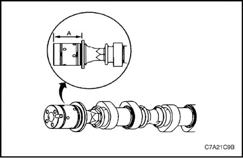
4. Using a bore micrometer, measure the degree of wear across the width of the thrust pad (A).
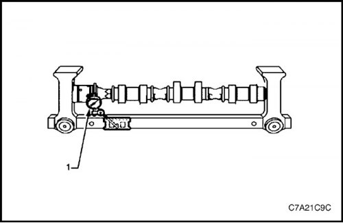
5. Measure the runout of the camshaft thrust wall surface using a dial indicator (1).
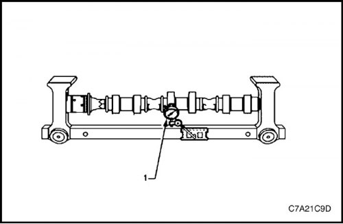
6. Measure the wear of the camshaft cams using a dial indicator (1).
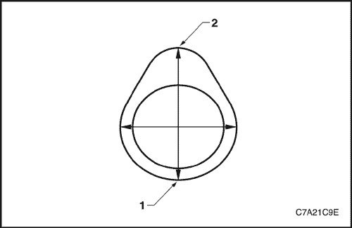
7. Place the tip of the dial indicator on the reference circle (1) of the camshaft cam.
8. Set the indicator to zero.
9. Rotate the camshaft until the tip of the indicator is at the point (2) of the cam that is furthest from the axis of rotation. This value represents the cam lift.
Installation procedure
Cylinder bank 1
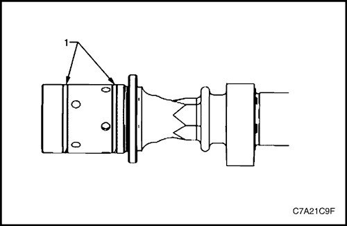
1. The camshaft sealing rings (1) must be in place in the grooves of the shaft.
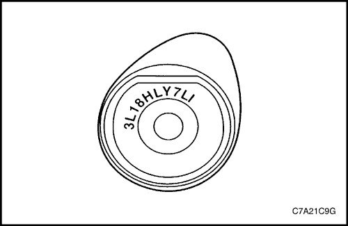
2. When installing a camshaft, it is important to correctly identify its purpose. The corresponding marking is located on the rear end of each camshaft. This marking contains the following information:
a. The first five positions indicate the date and time of manufacture.
- Example = 3L18H
b. Positions six through nine contain the engine production designation.
- LY7 = Alloytec190 engine
c. The last two positions indicate the position:
- LI = cylinder bank 2, intake.
- LE = cylinder bank 2, exhaust.
- RI = cylinder bank 1 intake.
- RE = cylinder bank 1, exhaust.
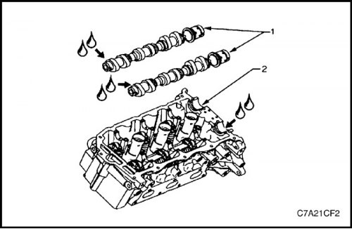
3. Generously lubricate the journals (1) of the camshafts and the bearings (2) of the camshafts of cylinder bank 1 with engine oil.
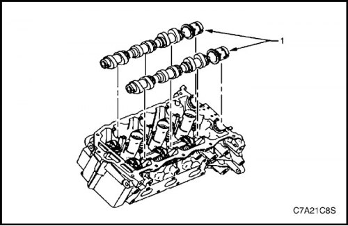
4. Generously lubricate the journals (1) of the camshafts and the bearings (2) of the camshafts of cylinder bank 1 with engine oil.
Note: Install the camshaft timing actuator bolts, but do not tighten them at this stage.
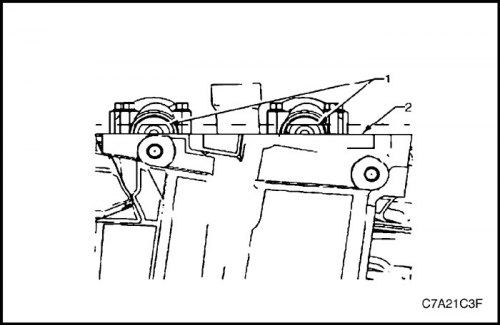
5. The camshafts must be positioned so that their cams are in the neutral position and the flats on the rear ends of the shafts of cylinder bank 1 are on top and parallel (1) to the joint surface (2) with the cylinder head cover.
6. Align the marks made before disassembly on the valve timing drive of the exhaust camshaft of cylinder bank 1 and on the drive chain.
7. Align the marks made before disassembly on the intake camshaft timing drive for cylinder bank 1 and on the drive chain.
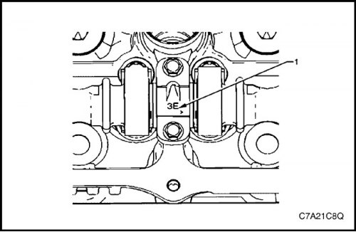
8. It is necessary to pay attention to the marking on the bearing caps of the camshafts of cylinder bank 1. Each bearing cap has a marking (1) that determines its location. This marking contains the following information:
- The raised area should always be oriented towards the center of the cylinder head.
- The letter I stands for intake camshaft.
- The letter E stands for exhaust camshaft.
- Numbers 1, 3, 5 indicate the position of the cylinder, counted from the front of the engine.
9. Generously lubricate the camshaft bearing caps with engine oil.
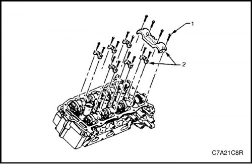
10. Generously lubricate the camshaft bearing caps with engine oil.
11. Install the remaining bearing caps (2), aligning their alignment marks towards the center of the cylinder head.
12. Tighten all camshaft bolt cover bolts (3) by hand.
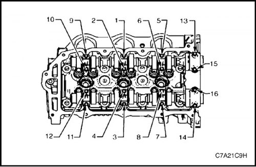
13. Install the camshaft bearing head bolts.
Tighten
Tighten the camshaft bearing cap bolt to 10 N·m (89 lb-in.).
14. Loosen bolts 1 and 2 of the intake camshaft center bearing cover and bolts 3 and 4 of the exhaust camshaft center bearing cover.
15. Retighten bolts 1, 2, 3 and 4 of the camshaft central bearing caps.
Tighten
Tighten the camshaft bearing cap bolt to 10 N·m (89 lb-in.).
16. Install the camshaft timing control drives for cylinder bank 1. See "Valve timing drive assembly" in this section.
Cylinder bank 2
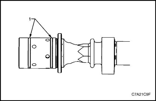
1. The camshaft sealing rings (1) must be in place in the grooves of the shaft.
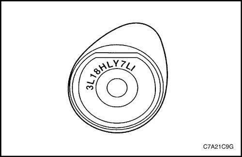
2. When installing a camshaft, it is important to correctly identify its purpose. The corresponding marking is located on the rear end of each camshaft. This marking contains the following information:
a. The first five positions indicate the date and time of manufacture.
- Example = 3L18H
b. Positions six through nine contain the engine production designation.
- LY7 = Alloytec 190 engine
c. The last two positions indicate the position:
- LI = cylinder bank 2, intake.
- LE = cylinder bank 2, exhaust.
- RI = cylinder bank 1 intake.
- RE = cylinder bank 1, exhaust.
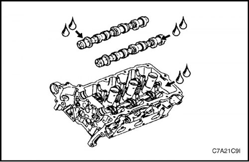
3. Generously lubricate the camshaft journals and camshaft bearings of cylinder bank 2 with engine oil.
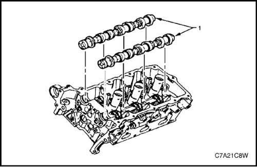
4. Position the camshafts (1) on the cylinder head and install the valve timing drives on the shafts.
Note: Install the camshaft timing actuator bolts, but do not tighten them at this stage.
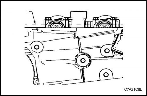
5. The camshafts must be positioned so that their cams are in the neutral position and the flats on the rear ends of the shafts of cylinder bank 2 are on top and parallel to the joint surface with the cylinder head cover.
6. Align the marks made before disassembly on the valve timing drive of the exhaust camshaft of cylinder bank 2 and on the drive chain.
7. Align the marks made before disassembly on the intake camshaft timing drive for cylinder bank 2 and on the drive chain.
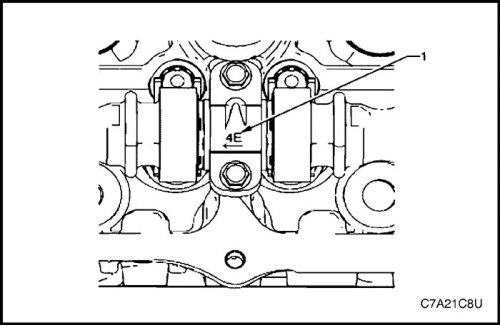
8. It is necessary to pay attention to the marking on the bearing caps of the camshafts of cylinder bank 2. Each bearing cap has a marking (1) that determines its location. This marking contains the following information:
- The raised area should always be oriented towards the center of the cylinder head.
- The letter I stands for intake camshaft.
- The letter E stands for exhaust camshaft.
- Numbers 2, 4, 6 indicate the position of the cylinder, counting from the front of the engine.
9. Generously lubricate the camshaft bearing caps with engine oil.
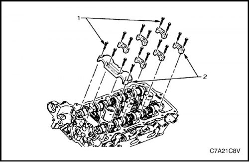
10. Install the cover (1) of the camshaft thrust bearing on the first journal of cylinder bank 2.
11. Install the remaining bearing caps (2), aligning their alignment marks towards the center of the cylinder head.
12. Tighten all camshaft bolt cover bolts (3) by hand.
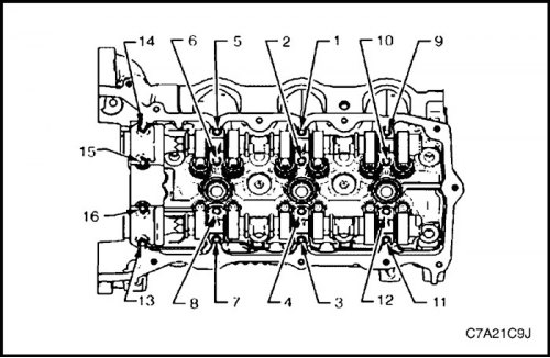
13. Install the camshaft bearing head bolts.
Tighten
Tighten the camshaft bearing cap bolt to 10 N·m (89 lb-in.).
14. Loosen bolts 1 and 2 of the intake camshaft center bearing cover and bolts 3 and 4 of the exhaust camshaft center bearing cover.
15. Retighten bolts 1, 2, 3 and 4 of the camshaft central bearing caps.
Tighten
Tighten the camshaft bearing cap bolt to 10 N·m (89 lb-in.).
16. Install the camshaft timing control drives for cylinder bank 2. See "Valve timing drive assembly" in this section.