
ChevyMan.ru
Mazda Mitsubishi Toyota Land Rover Honda Kia Nissan
English Русский
Български
Беларускі
Український
Српски
Hrvatski
Română
Polski
Slovenský
Magyar
|
Articles | Sitemap | Contacts |


Home   Aveo   Captiva   Cruze   Lacetti   Lanos   Niva   Tahoe   Others  
Captiva 1 (2006-2018)
  • Home
  • Captiva
  • 1 (2006-2018)
  • Engine HFV6 3.2L
  • Engine repair
  • Cylinder head assembly

Cylinder head assembly (Chevrolet Captiva 1)

            0

Contents: Removal procedure ↧ Installation procedure ↧

Removal procedure


Cylinder bank 1


1. Remove the engine assembly. Follow step "Engine assembly" in this section.

2. Remove the intake manifold. See "Intake manifold assembly" in this section.

3. Remove the exhaust manifold. See "Exhaust manifold assembly" in this section.

4. Remove the bolts securing the ground contacts of the engine wiring harnesses from the cylinder head.

5. Remove the secondary timing chain for cylinder bank 1. See "Camshaft Drive Chain Components" in this section.

6. Remove the valve timing actuators. See "Valve timing drive assembly" in this section.

7. Remove the power steering fluid supply line mounting bolt from the cylinder head.

8. Remove the cylinder head mounting bolts (1) (eight seats).

Note: There is no bolt provided for the hole in cylinder bank 1 of the cylinder head.


9. Remove the cylinder head.
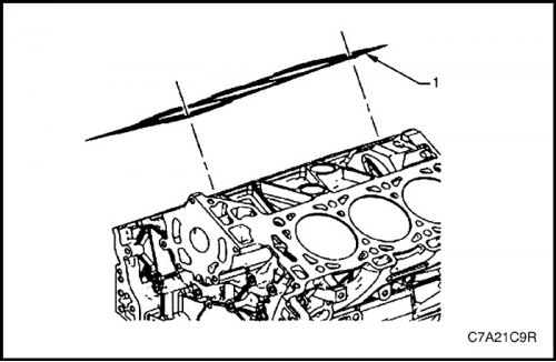
9. Remove the cylinder head.


10. Remove and discard the cylinder head gasket (1).
10. Remove and discard the cylinder head gasket (1).


Cylinder bank 2


1. Remove the engine assembly. Follow step "Engine assembly" in this section.


2. Remove the intake manifold. See "Intake manifold assembly" in this section.

3. Remove the exhaust manifold. See "Exhaust manifold assembly" in this section.

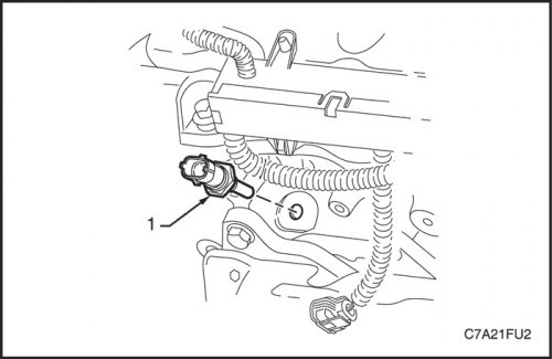
4. Remove the coolant temperature (ECT) sensor. See Section 1F3, Engine Controls - HFV6 3.2L.
4. Remove the coolant temperature (ECT) sensor. See Section 1F3, Engine Controls - HFV6 3.2L.


5. Remove the engine wiring harness ground contact mounting bolt from the cylinder head.

6. Remove the secondary timing chain for cylinder bank 2. See "Camshaft Drive Chain Components" in this section.

7. Remove the valve timing actuators. See "Valve timing drive assembly" in this section.

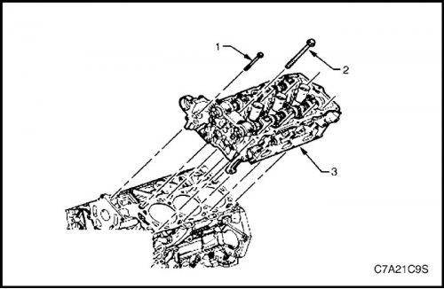
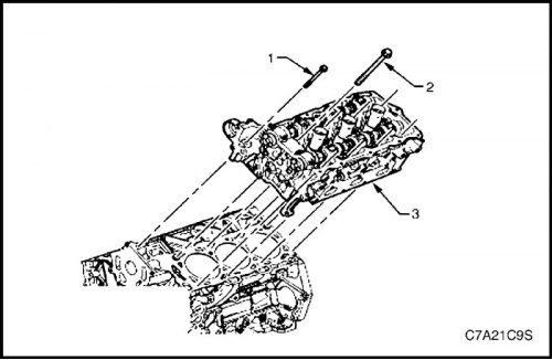
8. Remove the front cylinder head mounting bolts (1) (two places).

9. Remove the cylinder head mounting bolts (2) (eight seats).

10. Remove the cylinder head (3).
10. Remove the cylinder head (3).


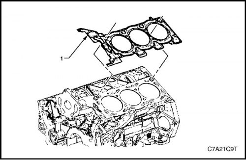
11. Remove and discard the cylinder head gasket (1).
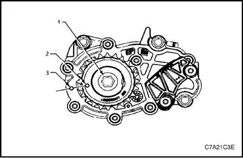


11. Remove and discard the cylinder head gasket (1).


Installation procedure


Cylinder bank 1


1. Installation should be carried out in the reverse order of removal of parts.

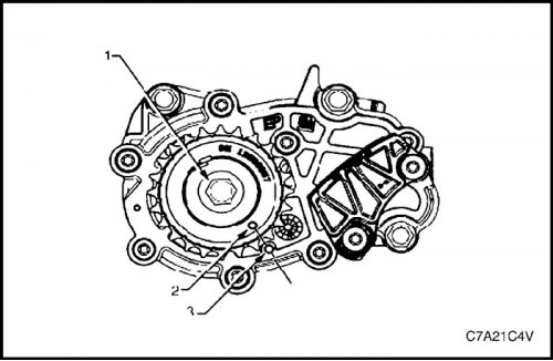
2. Using the EN-46111 tool (1) for turning the crankshaft, align the timing mark (2) on the crankshaft sprocket with the mark (3) on the oil pump housing.
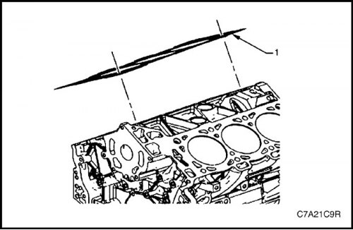
2. Using the EN-46111 tool (1) for turning the crankshaft, align the timing mark (2) on the…


3. Ensure that the surface of the block-cylinder head joint is clean and that the pins for installing the head are securely fastened to it.

4. Install a new cylinder head gasket (1), using the dowel pins on the mating surface to secure it.
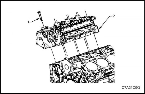
4. Install a new cylinder head gasket (1), using the dowel pins on the mating surface to secure it.


5. Correctly position the cylinder head relative to the dowel pins.


6. Install the cylinder head into place.

Note: It is necessary that there is no oil on the bolt bosses on the cylinder head.


Caution: Cylinder head bolts must not be reused (from 1st to 8th inclusive).

Caution: Cylinder head bolts must not be reused (from 1st to 8th inclusive).


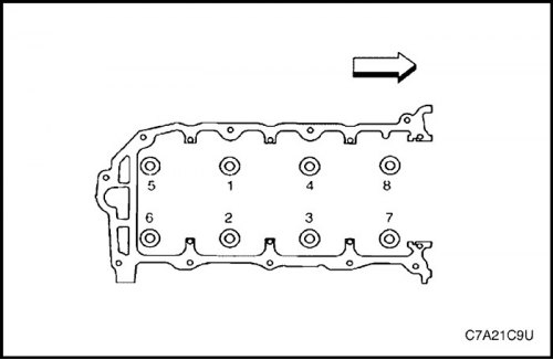
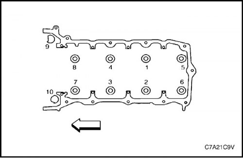
7. Install a new cylinder head bolt (1) (eight seats) and tighten in the sequence shown.

Tighten

Tighten the cylinder head bolts to 45 N·m (33 lb-ft) and turn the bolts an additional 120° using the angular torque gauge KM-470-B.

8. Install all previously removed external parts.
8. Install all previously removed external parts.


Cylinder bank 2


1. Installation should be carried out in the reverse order of removal of parts.

2. Using the EN-46111 tool (1) for turning the crankshaft, align the timing mark (2) on the crankshaft sprocket with the mark (3) on the oil pump housing.


2. Using the EN-46111 tool (1) for turning the crankshaft, align the timing mark (2) on the…


3. Ensure that the surface of the block-cylinder head joint is clean and that the pins for installing the head are securely fastened to it.

4. Install a new cylinder head gasket (1), using the dowel pins on the mating surface to secure it.
4. Install a new cylinder head gasket (1), using the dowel pins on the mating surface to secure it.


5. Correctly position the cylinder head relative to the dowel pins.

6. Install the cylinder head into place.

Note: It is necessary that there is no oil on the bolt bosses on the cylinder head.


Caution: Cylinder head bolts must not be reused (from 1st to 8th inclusive).

Caution: Cylinder head bolts must not be reused (from 1st to 8th inclusive).


7. Install a new cylinder head bolt (1) (eight seats) and tighten in the sequence shown.


Tighten

Tighten the cylinder head bolts to 45 N·m (33 lb-ft) and turn the bolts an additional 120° using the angular torque gauge KM-470-B.

8. Install the front cylinder head bolt (2) (two places) and tighten in the sequence shown (9 and 10).

Tighten

Tighten the front cylinder head bolts to 15 N·m (11 lb-ft) and turn each bolt an additional 60° using the angular torque gauge KM-470-B.

9. Install all previously removed external parts.
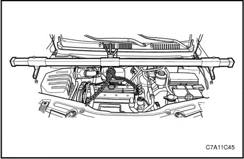
9. Install all previously removed external parts.


The source of the article is available on the website: «CHEVYMAN.RU»

The article was checked: Vladimir Romannikov
This article is available at russian, bulgarian, belarusian, ukrainian, serbian, croatian, romanian, polish, slovak, hungarian

Share information:

Previous articles
Captiva 1: Engine repair
Next articles

Stationary hydraulic valve clearance compensator
Removal and installation the rocker arm
Camshaft
Replacing the variable valve timing drive — row 1 (right side), intake
Replacing the variable valve timing drive — row 2 (left side), intake
Engine mount assembly (right side)
Gearbox mount assembly with final drive (left side)
Front suspension unit of the gearbox with the main gear assembly
Rear suspension unit of the gearbox with the main gear assembly
Removal and installation the engine


See similar articles on the topic of Chevrolet cars:
Replacing the cylinder head cover gasket Chevrolet Aveo T300 (2012-2018)
Replacing the cylinder head gasket Chevrolet Cruze 1 (2008-2016)
Replacing the cylinder head cover gasket Chevrolet Lacetti 1 (2002-2009)
Replacing the cylinder head cover gasket Chevrolet Lanos T150 (2002-2009)
Cylinder head and valve mechanism Chevrolet Niva 1 (2002-2016)
Cylinder Head Cover — Removal and Installation Chevrolet Tahoe 1 (1992-2000)
Removal and installation the cylinder head Chevrolet Lumina 1 (1989-1994)
Link in different formats to this page


Visitor comments

No comments yet


How much will 31 + 19 =


Captiva 1 (2006-2018) 
  • Manual
  • Before leaving
  • Keys, doors and windows
  • Seats, protection systems
  • Instruments and controls
  • Lighting system
  • Information and entertainment
  • Navigation system
  • Climate control
  • Driving a car
  • Car care
  • Maintenance
  • Engine 2.0 l (diesel)
  • Engine device
  • Troubleshooting
  • Engine repair
  • Cooling system
  • Engine electrical equipment
  • Control and power systems
  • Exhaust system
  • Engine FAM II 2.4D
  • Engine device
  • Troubleshooting
  • Engine repair
  • Cooling system
  • Engine electrical equipment
  • Control and power systems
  • Exhaust system
  • Engine HFV6 3.2L
  • Engine device
  • Troubleshooting
  • Engine repair
  • Cooling system
  • Engine electrical equipment
  • Control and power systems
  • Exhaust system
  • Transmission
  • Front drive axle
  • Rear drive axle
  • Automatic gearbox - device
  • Automatic gearbox - service
  • Automatic gearbox - repair
  • Manual gearbox - device
  • Manual gearbox - service and repair
  • Clutch
  • Transfer case
  • Chassis
  • Car suspension
  • Brake system
  • Steering
  • Body
  • Heating and ventilation
  • Air conditioning (manual)
  • Air conditioning (automatic)
  • Seat belts
  • Airbags
  • Car seat
  • Interior (internal elements)
  • Exterior (external elements)
  • Doors and windows
  • Electrical equipment
  • Equipment and devices
  • Lighting and lamps
  • Windshield wipers and washers
  • Electrical circuits


ChevyMan.ru © 2017-2026 · Mobile version · Feedback · Site search · Interesting to read · Sitemap: EN BG BY UA RS HR RO PL SK HU

Aveo 2003-2008 · Aveo 2006-2011 · Aveo 2012-2018 · Captiva 2006-2018 · Cruze 2008-2016 · Lacetti 2002-2009 · Lanos 2002-2009 · Niva 2002-2016 · Tahoe 1992-2000 · Tahoe 2000-2014 · Lumina 1 1989-1994 · Trailblazer 1 2001-2008 · Orlando 1 2010-2018 ·
🛡️ For your security and to improve our service, this site uses cookies. You can disable them in your browser.