


Contents: Removal procedure ↧ Installation procedure ↧
Necessary equipment
EN-48243 Engine assembly removal/installation rack
EN-48244 Rack bracket for engine assembly removal/installation
Removal procedure
1. Remove the fuel pump fuse.
2. Start the engine. After the engine stops, crank the engine for 10 seconds to relieve pressure in the fuel system.
3. Drain the engine oil.
4. Drain the engine coolant. See Part 1D3, Cooling of the HFV6 3.2L engine.
5. Drain the power steering oil.
6. Drain the transmission oil. See Section 5A, AISIN 55-51LE Automatic Transmission with Final Drive Assembly or Section 5B, Five-speed gearbox with final drive assembly (D33).
7. Discharge the air conditioning system, if equipped. Follow section 7B, Heating, Ventilation, and Air Conditioning Systems Control.
8. Remove the decorative engine cover. See "Decorative Engine Cover" in this section.
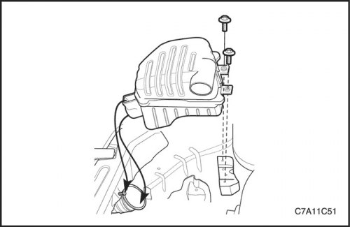
9. Remove the air cleaner assembly. See "Air filter assembly" in this section.
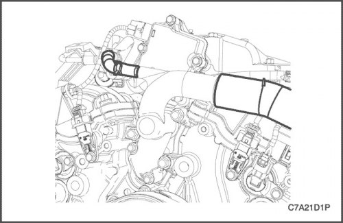
10. Disconnect the upper radiator hose from the water outlet.
11. Disconnect the water hose from the water outlet.
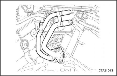
12. Disconnect the lower radiator hose from the water pipe.
13. Disconnect the heater inlet/outlet hose from the heater inlet/outlet pipe.
14. Disconnect the power steering hoses from the power steering fluid reservoir. See section 6A, Power Steering System.
15. Remove the battery. See Part 1E3, Engine Electrical - HFV6 3.2L.
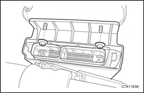
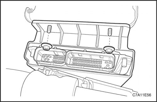
16. Remove the ECM. See Section 1F3, Engine Controls - HFV6 3.2L.
17. Disconnect the main engine fuse box cable.
18. Disconnect the ground terminal wiring harness.
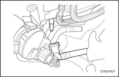
19. Disconnect the fuel line.
20. Disconnect the front Evaporative Canister Purge Hose from the Evaporative Canister Purge Solenoid Valve.
21. Disconnect the brake booster vacuum hose from the rear cylinder head cover.
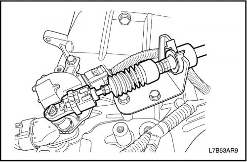
22. Disconnect the transmission range sensor electrical connector. See Section 5A, AISIN 55-51LE Automatic Transmission with Final Drive Assembly or Section 5B, Five-speed gearbox with final drive assembly (D33).
23. Disconnect the gear shift control cable from the transmission.
24. Disconnect the transmission coolant oil pipe from the radiator. See Section 5A, "AISIN 55-51 Automatic Transmission Assembled with Final Drive".
25. Disconnect the transmission cooling system oil pipe from the radiator. See Section 5B, Five-speed manual transmission with final drive assembly (D33).
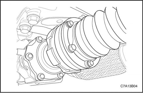
26. Disconnect the stabilizer bar mount. See Section 2D, Rear Suspension.
27. Disconnect the tie rod end connection. See Section 2D, Rear Suspension.
28. Disconnect the steering rod connection. See Section 2D, Rear Suspension.
29. Remove the left and right axle shafts. See Section 3A, Front Drive Axle or Section 3B, Rear Drive Axle.
30. Disconnect the intermediate shaft from the power steering gear. See Section 6C, Power Steering.
31. Remove the propeller shaft. See Section 3B, Rear Drive Axle.
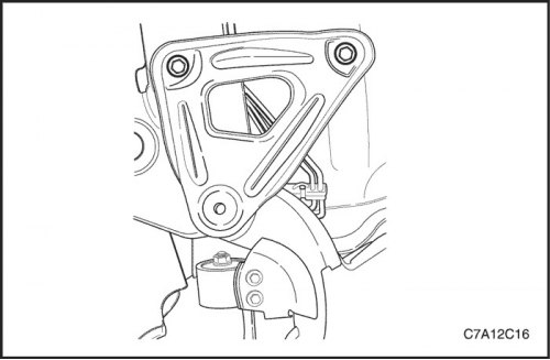
32. Remove the strut bracket bolts from the rear of the strut.
33. Remove the strut bracket bolts from the front of the strut.
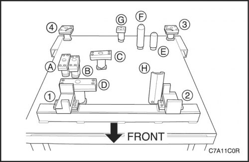
Caution: Make sure that all components are installed exactly in the required position on the EN-48243 motor removal/installation rack or EN-48244 bracket as shown in the figure.
- 1~4: Support bracket
- A: Diesel engine oil pan bracket
- B: FAM II 2.4D Engine Oil Pan Bracket
- C & D: HFV6 3.2L Engine Oil Pan Bracket
- E: Bracket of manual transmission with final drive assembly
- F: Automatic transmission bracket with final drive assembly
- G: Transfer Case Bracket ((M/T and A/T)
- H: Transaxle Mount Bracket (M/T and A/T)
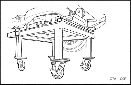
Caution: Lower the vehicle sufficiently to relieve the load on the engine mount and the transmission assembly, otherwise suspension damage and rack/rack bracket failure may occur.
34. Lower the vehicle and place the engine assembly on the EN-48243 Engine Assembly Rack with EN-48244 Rack Bracket until it rests.
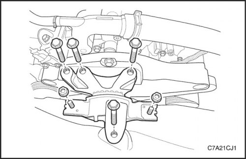
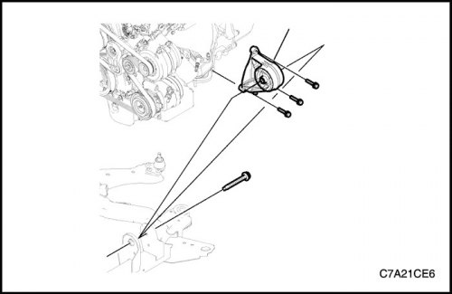
35. Remove the engine mount assembly. See "Engine mount unit" in this section.
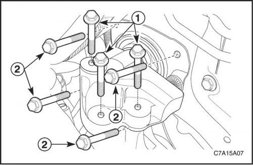
36. Remove the transmission mount assembly with the final drive assembly. See "Gearbox suspension with final drive assembly" in this section.
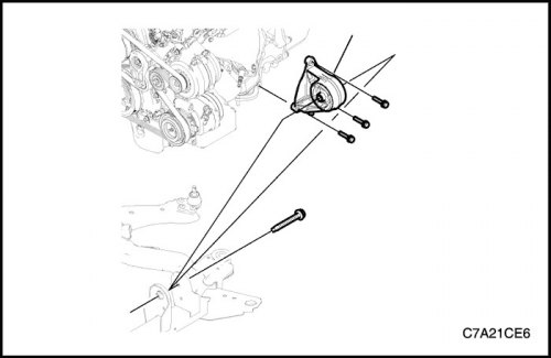
Caution: Make sure all wires, connectors and hoses are disconnected from the engine and transaxle assembly.
37. Raise the vehicle to freely remove the engine and gearbox with the final drive assembly.
38. Remove the engine and gearbox with the final drive assembly from the vehicle
39. Install a lifting device on the engine support bracket and raise the engine assembly to remove load from the front and rear suspension of the transaxle assembly.
40. Remove the front transmission suspension with the final drive assembly from the support. See "Front suspension of the gearbox with the main gear assembly" in this section.
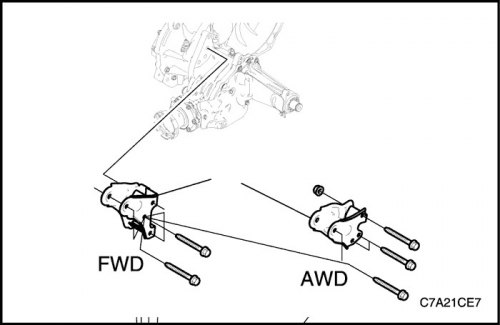
41. Remove the rear suspension of the gearbox with the final drive assembly from the support. See "Rear suspension of the gearbox with the main gear assembly" in this section.
42. Raise the engine assembly and remove the support from the engine and gearbox assembly.
43. Separate the cylinder block from the gearbox with the final drive assembly as follows.
- a. Remove the starter.
- b. Loosen the torque converter bolts.
- c. Loosen the mounting bolts connecting the gearbox with the final drive assembly to the engine cylinder block.
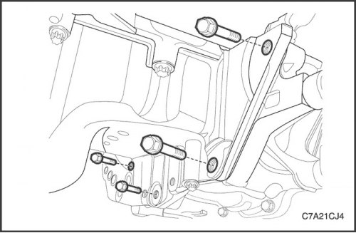
- d. Loosen the mounting bolts connecting the oil flange to the gearbox with the final drive assembly.
Installation procedure
1. Install torque converter bolts if required.
Tighten
Tighten the torque converter bolts to 65 N·m (48 lb-ft).
2. Install the gearbox and final drive assembly onto the engine block if required.
Tighten
Tighten the oil pan flange to transaxle assembly bolts to 50 N·m (37 lb-ft).
Tighten the transmission assembly mounting bolts to the cylinder block (upper side of gearbox - 3 pcs., Starter side - 1 pc., Rear side of gearbox - 1 pc.) torque of 50 N·m (37 lb-ft).
Caution: Ensure that all components of the EN-48243 Engine Assembly Removal/Installation Rack are aligned precisely with the EN-48244 Rack Bracket.
3. Install the engine and gearbox with the final drive assembly on the support.
Caution: Before tightening the front transmission mount clamp bolt, move the engine assembly back and forth or side to side to ensure proper installation.
4. Install the front suspension unit of the gearbox with the final drive assembly.
Tighten
Tighten the transaxle front mount retaining bolts to 50 N·m (37 lb-ft).
Tighten the front transaxle mount to support pinch bolt to 90 N·m (66 lb-ft).
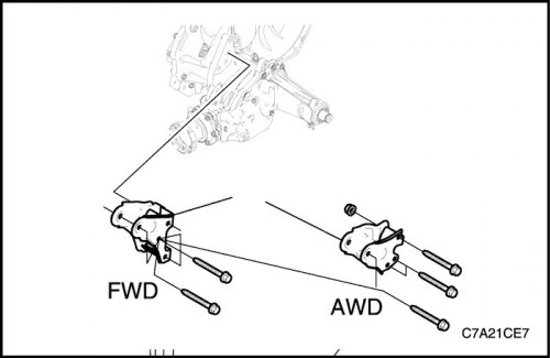
Caution: Before tightening the rear transmission mount clamp bolt, move the engine assembly back and forth or side to side to ensure proper installation.
5. Install the rear suspension of the gearbox with the final drive assembly onto the engine cylinder block.
Tighten
Tighten the transaxle rear mount retaining bolts to 90 N·m (66 lb-ft).
Tighten the rear transaxle mount to bracket pinch bolt to 90 N·m (66 lb-ft).
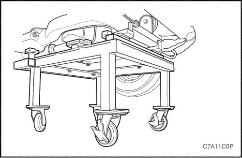
6. Raise the car.
7. Lower the vehicle and place the engine and gearbox assembly with the final drive connected to the support on the EN-48243 Engine Assembly Rack with EN-48244 Rack Bracket in the vehicle.
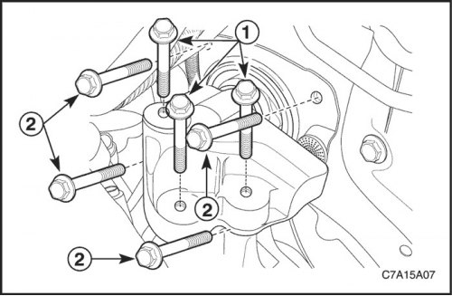
8. Install the gearbox mount with the final drive assembly. See "Gearbox suspension with final drive assembly" in this section.
Tighten
Tighten the transaxle mount retaining bolts to 37 N·m (27 lb-ft).
Tighten the transaxle mount bracket retaining bolts to 50 N·m (37 lb-ft).
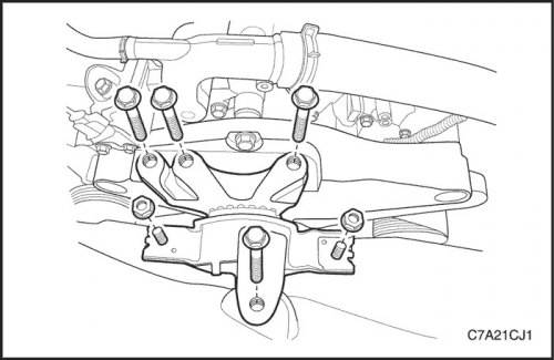
9. Install the engine mount assembly. See "Engine mount unit" in this section.
Tighten
Tighten the engine mount frame side bracket retaining bolt to 100 N·m (74 lb-ft) and the nuts to 90 N·m (66 lb-ft).
Tighten the engine mount adapter retaining bolts to 50 N·m (37 lb-ft).
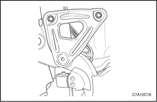
10. Install the support bracket mounting bolts to the front of the support.
Tighten
Tighten the support mounting bolts to 155 N·m (114 lb-ft).
11. Tighten the support bracket bolts to 50 N·m (37 lb-ft).
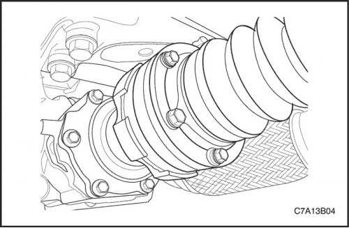
12. Attach the stabilizer bar mount. See Section 2D, Rear Suspension.
13. Attach the tie rod end. See Section 2D, Rear Suspension.
14. Connect the steering rod. See Section 2D, Rear Suspension.
15. Install the left and right axle shafts. See Section 3A, Front Drive Axle or Section 3B, Rear Drive Axle.
16. Attach the intermediate shaft to the power steering gear. See Section 6C, Power Steering.
17. Install the propeller shaft. See Section 3B, Rear Drive Axle.
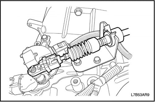
18. Connect the electrical connector of the transmission mode sensor. See Section 5A, AISIN 55-51LE Automatic Transmission with Final Drive Assembly or Section 5B, Five-speed gearbox with final drive assembly (D33).
19. Connect the gear shift control cable to the gearbox.
20. Connect the transmission coolant oil pipe to the radiator. See Section 5A, "AISIN 55-51 Automatic Transmission Assembled with Final Drive".
21. Connect the power steering fluid coolant return line. See section 6A, Power Steering System.
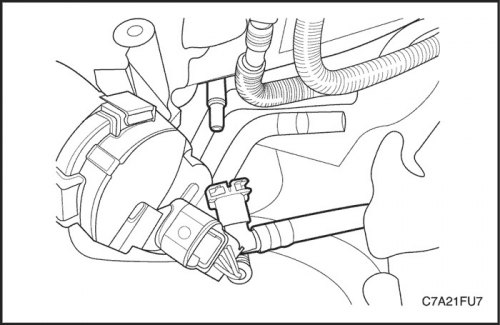
22. Connect the fuel line.
23. Connect the front Evaporative Canister Purge Hose to the Evaporative Canister Purge Solenoid Valve.
24. Connect the brake booster vacuum hose to the rear cylinder head cover.
25. Install the battery. See Part 1E3, Engine Electrical - HFV6 3.2L.
26. Install the ECM. See Section 1F3, Engine Controls - HFV6 3.2L.
27. Connect the main engine fuse box cable.
28. Connect the ground terminal wire harness.
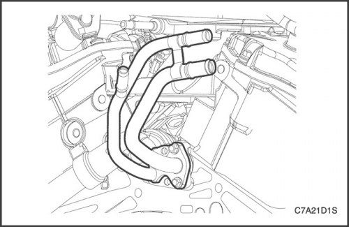
29. Connect the lower radiator hose to the water pipe.
30. Connect the heater inlet/outlet hose to the heater inlet/outlet pipe.
31. Connect the power steering hoses to the power steering fluid reservoir. See section 6A, Power Steering System.
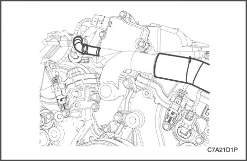
32. Disconnect the upper radiator hose from the water outlet.
33. Disconnect the water hose from the water outlet.
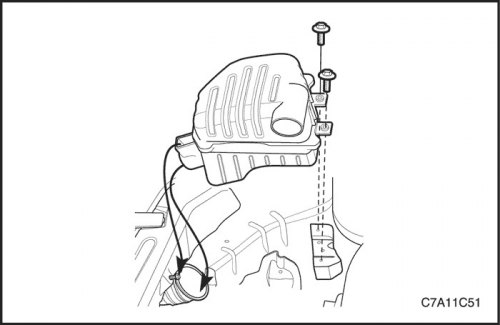
34. Remove the decorative engine cover. See "Decorative Engine Cover" in this section.
35. Remove the air cleaner assembly. See "Air filter assembly" in this section.
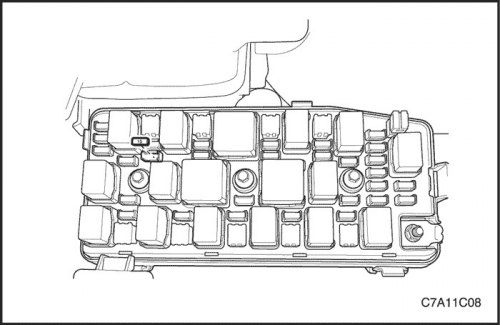
36. Install the fuel pump fuse.
37. Fill the crankcase with engine oil.
38. Fill the engine cooling system. See Part 1D3, Cooling of the HFV6 3.2L engine.
39. Refill the power steering system and bleed the system. See section 6A, Power Steering System.
40. Refill the air conditioning refrigeration system, if equipped. Follow section 7B, Heating, Ventilation, and Air Conditioning Systems Control.
41. Check for leaks or unusual sounds and that all fluid levels are sufficient.
(The article is reprinted from the website «ChevyMan»)