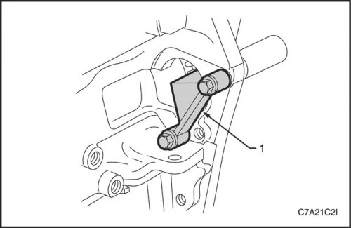
Contents: Removal procedure ↧ Disassembly ↧ Clear ↧ Inspection ↧ Assembly ↧ Installation procedure ↧
Removal procedure
1. Disconnect the negative battery cable.
2. Remove the engine assembly. Follow the step in this section.
3. Remove the front timing belt cover. See this section.
4. Remove the front exhaust pipe. See Part 1G3, Engine exhaust system.
5. Disconnect the oil level sensor connector.
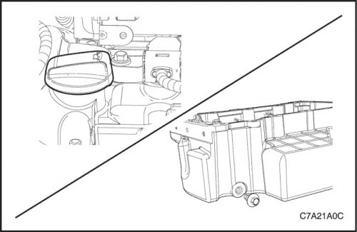
6. Remove the oil filler cap to allow the oil to drain.
7. Remove the oil pan drain plug and drain the oil into a suitable container.
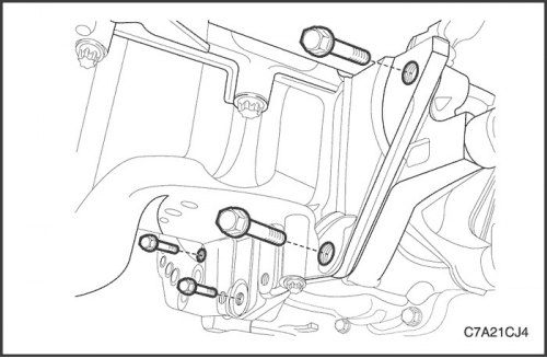
8. Remove the oil pan flange retaining screws from the transaxle assembly.
9. Remove the transfer case bracket mounting bolts. See Part 5D. "Transfer case".
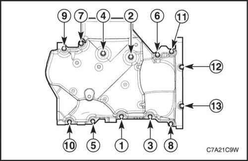
10. Remove the two long bolts (12 and 13) that secure the rear of the oil pan to the crankshaft rear oil seal housing.
11. Remove eleven bolts (from 1st to 11th), which secure the oil pan to the cylinder block.
12. Using the support points located at the edges of the oil pan, separate the oil pan held in place with RTV sealant.
13. Remove the oil pan from the cylinder block.
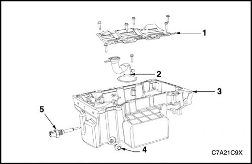
Disassembly
1. Oil pan (3), drain plug (4) and bushing.
2. Oil level sensor (5).
3. Crankshaft oil deflector bolts and oil deflector (1).
4. Oil pump suction pipe bolts and suction pipe (2).
5. Gasket from the suction pipe of the oil pump; discard the gasket.
Clear
1. Remove any remaining thread sealant, gasket material and sealant using a standard wooden or plastic scraper.
2. Wash the oil pan and its components in solvent.
3. Remove all dirt from bolt holes.
4. Dry the oil pan and its components with compressed air.
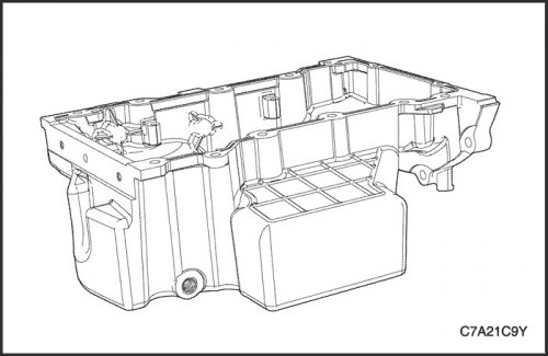
Inspection
1. Inspect the oil pan from the outside, checking for the following faults:
- Damage to the drain plug or drain hole
- Damage to the mounting bosses for fastening the gearbox
- Damage to the oil level sensor threads
- Chips or damage to the cover on the outside.
2. Dry the oil pan and its components with compressed air.
- Chips or damage to the sealing surfaces of the oil pan
- Damage to the crankshaft oil deflector
- Damage to bolt holes
- Damage to the mounting bosses of the oil suction pipe
- Damage to the mounting bosses of the crankshaft oil deflector.
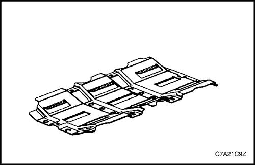
3. Inspect the oil pan damper for damage.
4. Repair or replace the oil pan and/or its components as necessary.
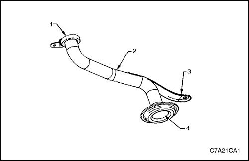
5. Check the following:
- A. The joint surface (1) of the oil pump suction pipe, which may have defects that lead to leakage.
- B. The suction pipe (2) of the oil pump, which may have cracks, defects and/or damage.
- C. Oil pump pipe bracket (3), which may have cracks or damage.
- D. The oil pump strainer (4) may be clogged, blocked, torn and/or damaged.
6. Repair or replace the oil pan and/or its components as necessary.
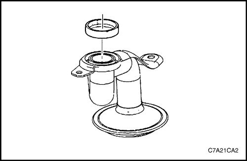
Assembly
1. Install a new seal on the oil suction pipe.
2. Install the oil suction pipe and tighten the bolts.
- Chips or damage to the sealing surfaces of the oil pan
- Damage to the crankshaft oil deflector
- Damage to bolt holes
- Damage to the mounting bosses of the oil suction pipe
- Damage to the mounting bosses of the crankshaft oil deflector.
Tighten
Tighten the oil suction pipe retaining bolts to 10 N·m (89 lb-in.).
3. Install the crankshaft oil deflector into the oil pan and tighten the mounting bolts.
Tighten
Tighten the crankshaft oil deflector to oil pan bolts to 10 N·m (89 lb-ft).
4. Install the oil level sensor into the oil pan.
Tighten
Tighten the oil level sensor to 20 N·m (15 lb-in.).
5. Replace the oil pan drain plug.
Tighten
Tighten the oil pan drain plug to 25 N·m (18 lb-ft).
Installation procedure
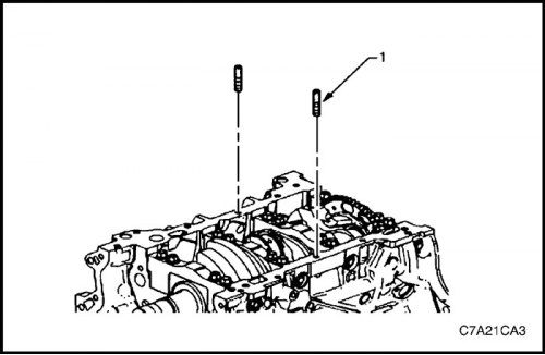
1. Install EN-46109 guide pins (1) into the bolt holes on the oil pan mating surface on both sides of the cylinder block.
Tighten
Tighten the intake manifold retaining bolts and nuts to 22 N·m (16 lb-ft).
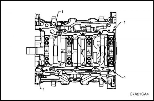
2. Apply a 3 mm wide bead of RTV sealant (1) to the joint surfaces of the cylinder block and the crankshaft rear oil seal housing with the oil pan.
3. Install the oil pan onto the cylinder block.
4. Remove EN-46109 guide pins from the cylinder block.
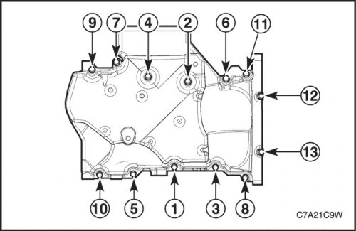
5. Install the oil pan mounting bolts without tightening.
6. Tighten the oil pan bolts in the sequence shown.
Tighten
Tighten the oil pan to cylinder block bolts to 23 N·m (17 lb-ft).
Tighten the oil pan to crankshaft rear oil seal housing bolts (12 - 13) to 10 N·m (89 lb-in).
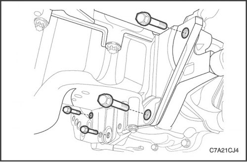
7. Remove the oil pan flange retaining screws from the transaxle assembly.
Tighten
Tighten the oil pan flange to transaxle assembly bolts to 50 N·m (37 lb-ft).
8. Remove the transfer case bracket mounting bolts. See Part 5D. "Transfer case".
9. Install the front timing belt cover. See this section.
10. Install the engine assembly. Follow the step in this section.
11. Install the oil pan drain plug.
Tighten
Tighten the oil pan drain plug to 25 N·m (18 lb-ft).
12. Install the front exhaust pipe. See Part 1G3, Engine exhaust system.
13. Pour engine oil into the oil pan.