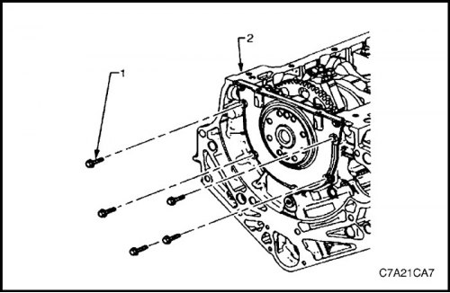
Removal procedure
1. Remove the engine assembly. See Part 1C2, "Engine Mechanical - HFV6 3.2L".
2. Remove the gearbox. See Section 5A, AISIN 55-51LE Automatic Transmission with Final Drive Assembly or Section 5B, Five-speed gearbox with final drive assembly (D33).
3. Remove the starter. See Part 1E3, Engine Electrical - HFV6 3.2L.
4. Install the EN-46106 drive disc holding device (1) at the starter mounting location.
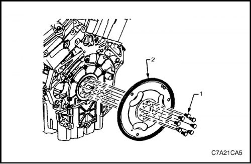
5. Loosen the eight bolts (1) securing the drive disc.
6. Remove the drive disc holding device.
7. Using a suitable felt-tip pen, make marks on the drive disk assembly (2) and on the crankshaft to indicate their relative positions.
8. Remove the eight drive disc mounting bolts and discard.
9. Remove the drive disc assembly.
Inspection
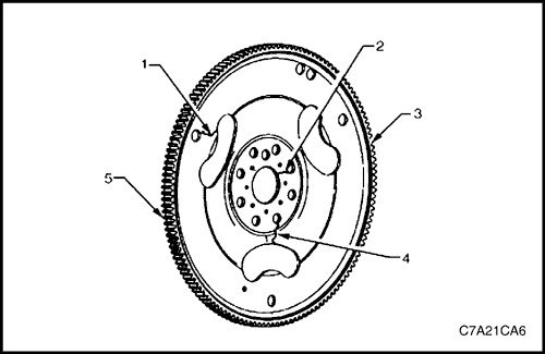
1. Inspect the drive disc assembly for the following faults:
- Cracks formed under the action of mechanical stress around the holes (1) for the bolts for fastening the drive disk to the torque converter.
- Cracks formed under the influence of mechanical stress around the holes (2 and 4) for the bolts for fastening the drive disk to the crankshaft.
Caution! Do not repair the welded joints of the toothed ring to the drive disk. The drive disk must be replaced.
- Cracks formed under the action of mechanical stress around the holes (1) for the bolts for fastening the drive disk to the torque converter.
- Damaged or missing teeth on the ring gear (5).
Note: The drive disk ring gear is not serviced separately and cannot be repaired. If it is found to be faulty or damaged, the entire drive disk must be replaced.
2. Replace the drive disc assembly if necessary.
Installation procedure
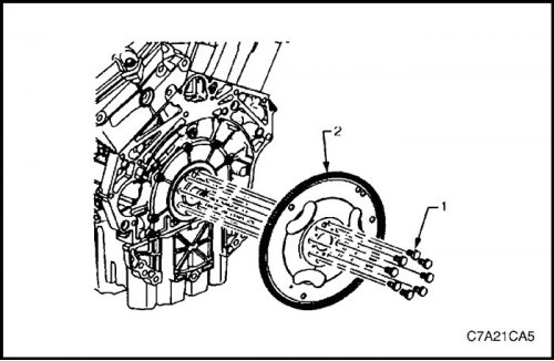
Note: The bolt holes are not evenly spaced to ensure that the drive disc can only be installed in one position.
1. Install the drive disc assembly (2) onto the crankshaft.
2. Install new drive disc mounting bolts (1) and tighten by hand.
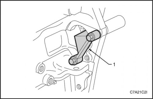
3. Install the EN-46106 drive disc holding device (1) at the starter mounting location.
4. Install the drive disc mounting bolts.
Tighten
Tighten the drive plate mounting bolts to 30 N·m (22 lb-ft) and tighten the bolts an additional 45° using the KM-470-B angular torque gauge.
5. Remove the drive disc holding device.
6. Install the generator. See Part 1E3, Engine Electrical - HFV6 3.2L.
7. Install the gearbox. See Section 5A, AISIN 55-51LE. Automatic Transmission with Final Drive Assembly or Section 5B, Five-speed gearbox with final drive assembly (D33).
8. Install the engine assembly. See Part 1C2, "Engine Mechanical - HFV6 3.2L".