


Removal procedure
1. Remove the engine assembly.
2. Remove both cylinder heads as an assembly.
3. Remove the oil pan assembly.
4. Remove the connecting rod and piston group as an assembly.
5. Remove the oil pump assembly.
6. Remove the rear oil seal and crankshaft cover assembly.
7. Remove the crankshaft position (CKP) sensor.
8. Unscrew the side bolts (3) securing the main bearing cap.
Caution! The outer main bearing cap mounting bolts are tightened with dynamic deformation during assembly and must be replaced before reassembly. The outer main bearing cap mounting bolts that are not replaced cannot be tightened to the correct clamping torque, which may cause serious engine damage.
9. Remove the outer bolts (1) securing the main bearing cap.
10. Remove the inner bolts (2) securing the main bearing cap.
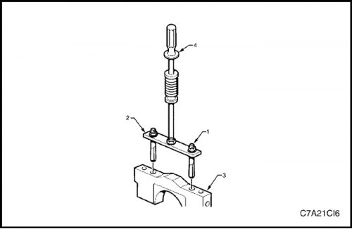
11. Loosen the nuts (1) of the crankshaft main bearing cap puller, Tool No. J-41818 (2), to separate the tapered bushings with chamfered edges. Insert the bushings into the inner bolt holes of the front main bearing cap (3).
12. Tighten the puller nuts to 11 N·m (97 lbs.in).
13. Install the slide hammer, tool No. J-6125-1B (4), on the main bearing cap puller and remove the main bearing cap.
14. Repeat steps 9 through 13 for the remaining main bearing caps.
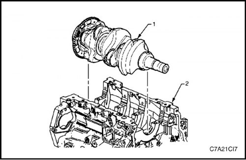
15. Remove the crankshaft (1) from the cylinder block (2), lifting it evenly to avoid pinching by the main thrust bearing.
16. Move the crankshaft to a safe location.
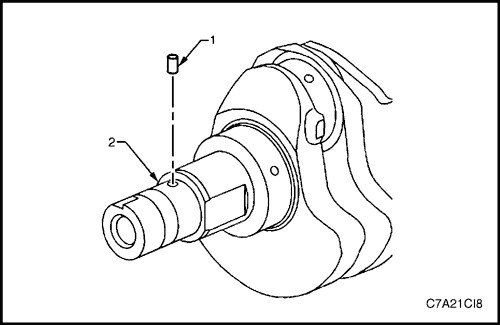
17. If necessary, remove the crankshaft sprocket drive pin (1) from the crankshaft (2).
Measuring the axial clearance of the crankshaft
1. Install a dial indicator on the end of the front of the crankshaft.
2. Gently push the crankshaft towards the front and rear of the cylinder block with the lever, while observing the movement of the dial indicator.
3. The axial clearance of the crankshaft must not exceed the technical specifications.
4. If specifications are exceeded, inspect the thrust bearing outside diameter and crankshaft thrust wall for wear and/or excessive wear. Compare values with specifications.
5. Replace the thrust bearing or crankshaft if necessary.
Main bearing
1. Prepare a piece of cardboard or something similar with numbers 1 through 4 to mark the bearings.
Note: Main bearing journals are numbered from the front of the engine.
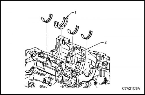
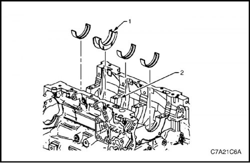
2. Remove the upper halves of the crankshaft bearings from the cylinder block. Note the position of the thrust bearing (1) on journal No.3 (2).
3. Place the top halves of the crankshaft bearings on the cardboard in the appropriate locations.
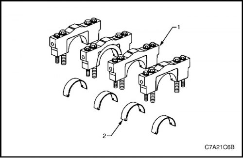
4. Remove the lower halves (2) of the crankshaft bearings from the main bearing caps (1).
5. Place the lower halves of the crankshaft bearings on the cardboard in the appropriate locations.
Cleaning and checking
Cleaning the crankshaft and main bearings
1. Clean the following components in solvent and then dry with compressed air:
- crankshaft bearings;
- Connecting rod bearings
- crankshaft journals;
- crankshaft connecting rod journals;
- channels for lubrication of the crankshaft, as well as
- crankshaft threaded holes.
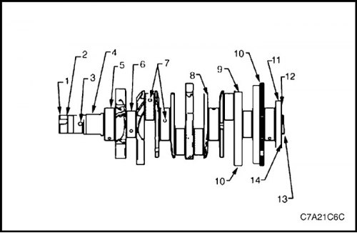
Inspection of the crankshaft and main bearings
1. Perform the following inspections:
- Check the hole (1) for the crankshaft vibration damper bolt for damage to the threads.
- Check the area (2) of the crankshaft vibration damper mounting for damage.
- Check the hole (3) for the crankshaft sprocket pin for damage.
- Check the flat surfaces (4) of the oil pump drive for damage.
- Check the crankshaft main journals (5) for damage.
- Check the crankshaft connecting rod journals (6) for damage.
- Check the lubrication channels (7) of the crankshaft for obstructions.
- Check the surfaces (8) of the crankshaft main bearing thrust wall for damage.
- Check the counterweights (9) of the crankshaft for damage.
- Checking the teeth of the crankshaft pulse sensor ring (10) for damage.
- Check the surface (11) of the rear main crankshaft oil seal for damage.
- Check the mounting surface (12) of the engine flywheel "flexplate" on the crankshaft for damage.
- Check the crankshaft bore (13) for damage.
- Check the holes (14) for the engine flywheel bolts on the crankshaft for thread damage.
2. Repair or replace the crankshaft if necessary.
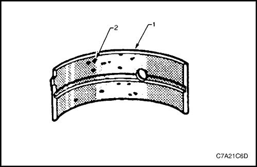
Checking the crankshaft main bearings
Caution! All connecting rod and main journal bearings that have been used on a running engine must be replaced. Never reuse crankshaft or connecting rod bearings.
Note: The following bearing wear conditions should be used to diagnose engine operating conditions or the root cause of the condition.
1. Check for fatigue, indicated by pits or cavities (2). Flattened parts of the bearing halves (1) also indicate fatigue.
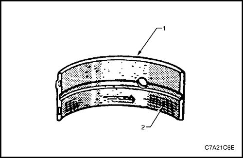
2. Check for excessive scoring or discoloration (2) on both the front and back sides of the bearing halves (1).
3. Checking the main bearings for dirt inclusions in the bearing material.
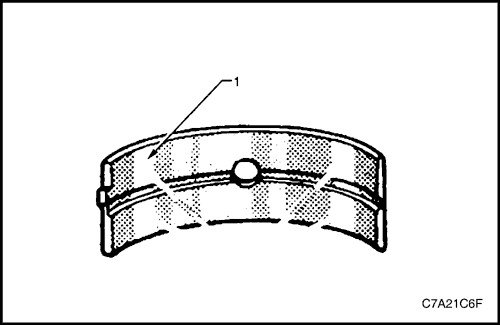
4. Check for improper fit, indicated by bright, polished parts (1).
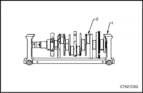
Crankshaft measurement
1. Use a suitable tool (1) to support the crankshaft (2).
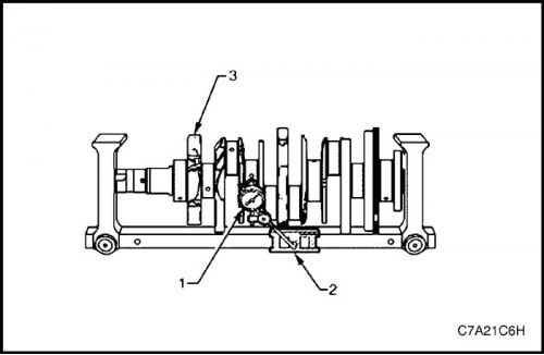
2. Using a dial indicator (1) and magnetic base (2), gently rotate the crankshaft (3) by hand. Measure the crankshaft journals for wear and compare with engine specifications.
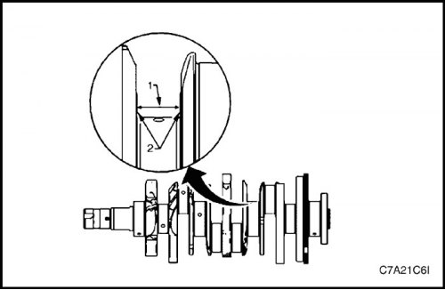
3. Measure the width (1) of the crankshaft thrust wall, taking into account wear, with an internal micrometer with engine specifications.
4. Measure the surface (2) of the crankshaft thrust wall, keeping in mind the wear, with a dial indicator mounted on a magnetic stand and compare with the engine specifications.
5. If the crankshaft journals are damaged or worn beyond specifications, the crankshaft can be ground down by 0.25 mm. There is only one oversize of oversize main bearings available for service.
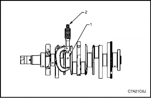
6. Check the crankshaft main journals (1), keeping in mind the reduction in size compared to the nominal value, with an outside micrometer (2).
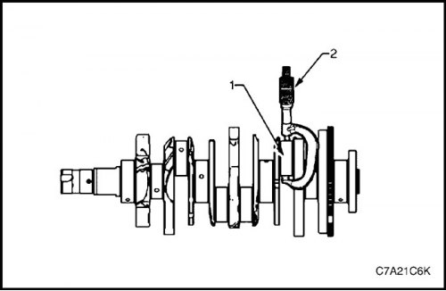
7. Check the crank pins (1), keeping in mind the reduction in size compared to the nominal value, with an outside micrometer (2).
8. Compare your measurements with the values listed in the engine specifications. If the crankshaft journals are worn beyond specification, the crankshaft can be ground down 0.25 mm. There is only one oversize of oversize connecting rod bearings available for service.
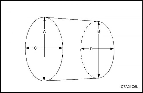
9. Measure the crankshaft main and connecting rod journals for out-of-roundness in the following order:
a. Using an outside micrometer, measure the journal in two places, the extreme front and extreme rear. Let's call these points A and B.
b. Measure the neck at two other points exactly 90 degrees from the first points. Let's call these points C and D.
c. Subtract A from C and B from D. These differences will indicate the ovality of the cervix.
d. The ovality should not exceed a maximum of 0.004 mm.
e. If the journals are worn beyond specification, the crankshaft can be ground down by 0.25 mm. There is only one oversize oversize crankshaft and oversize connecting rod bearings available for service.
10. If the journals are worn beyond specifications, the crankshaft can be ground down by 0.25 mm. There is only one oversize of oversize crankshaft and oversize connecting rod bearings available for service.
a. Using an outside micrometer, measure the journal at the extreme forward point (A) and the extreme rear point (B) of the journal parallel to the crankshaft centerline.
b. Subtract the smaller measurement from the larger measurement. The result is the neck taper.
c. If the taper of the main bearing journal exceeds 0.004 mm, replace the crankshaft.
d. If the journals are worn beyond specifications, the crankshaft can be ground down by 0.25 mm. There is only one oversize oversize crankshaft and oversize connecting rod bearings available for service.
Installation procedure
Main bearing installation procedure
Caution: If the crankshaft bearings have been used on a running engine, replace them with new crankshaft bearings during reassembly.
1. Clean the crankcase bore of the big end of the connecting rod with a lint-free cloth.
2. Clean all oil from the back of the new bearing halves.
3. Install new upper crankshaft bearings in their original position. The thrust bearing (1) fits journal No.3 (2). Make sure the upper bearing shell has a hole and a grease redistribution groove. Roll the bearing into its original position so that the locking lug fits into the groove in the crank. The bearing should sit flush with the upper crankcase.
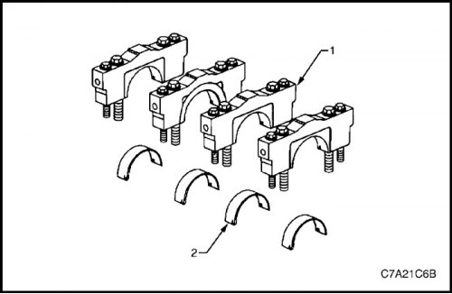
4. Install new lower crankshaft bearings (2) in their original positions in the main bearing caps (1). Lower crankshaft bearings are not grooved or bored. The bearings should be flush with the main bearing caps.
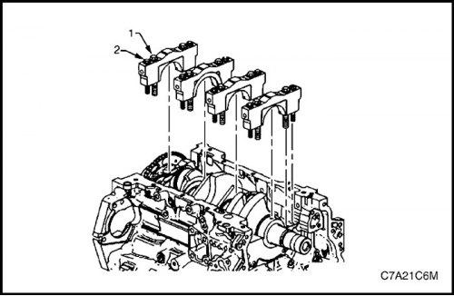
Measuring the crankshaft main bearing clearance
1. Place a piece of fresh, room temperature plastic measuring material across the entire length of each main bearing journal.
2. Install the crankshaft main bearing caps.
3. Loosely tighten the original inner bolts (1) of the main caps.
4. Loosely tighten the original outer bolts (2) of the main caps.
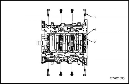
5. Loosely tighten the stock short/inner side main cap bolts.
6. Loosely tighten the original long/outer side bolts (3) of the main caps.
7. Use a soft-faced hammer to lightly tap the caps into place.
8. Tighten the main cap bolts.
Tighten
Tighten the crankshaft main bearing cap inner mounting bolt to 20 N·m (15 ft·lbs), plus another 80°.
Tighten the outer mounting bolt of the crankshaft main bearing cap to 15 N·m (11 ft·lbs), plus another 110°.
Tighten the crankshaft main bearing cap side mounting bolt to 30 N·m (22 ft·lbs), plus another 60°.
Note: Do not rotate the crankshaft.
9. Let the assembly sit for 2 minutes.
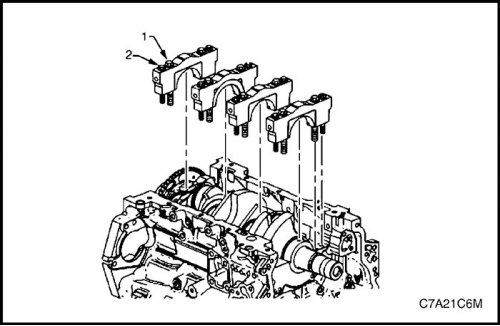
10. Remove the side bolts securing the main bearing cap.
11. Remove the outer bolts (2) securing the main bearing cap.
12. Remove the inner bolts (1) securing the main bearing cap.
13. Install the crankshaft main bearing cap puller, Tool No. J-41818, as described previously and remove the main bearing cap.
14. Repeat steps 10 through 13 for the remaining main bearing caps.
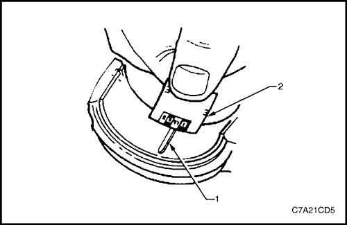
15. Determine the main bearing clearance by comparing the width of the flattened plastic measuring material (1) at its widest point with the divisions on the measuring scale (2).
16. Compare the measurements with the specifications. If the new bearings do not provide the correct clearance between the crankshaft and the bearing, check the following:
a. Measure the crankshaft journals to size and ensure new bearings are installed. If the crankshaft journals are not the correct size, replace or regrind the crankshaft. The crankshaft may be machined and undersized bearings are available.
b. Measure the diameter of the crankshaft bearing recess of the cylinder block and ensure that it is the correct size. The crankshaft bearing recess of the cylinder block cannot be machined, and if it does not meet the specifications, the block must be replaced.
17. Remove the plastic measuring material from the main bearing journals with a soft, lint-free cloth.
Final installation procedure for the crankshaft
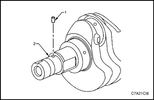
1. Install the crankshaft sprocket drive pin (1) if removed. Tap the pin into place with a small soft faced brass/plastic hammer until it bottoms out in the hole.
Caution: Before loading the crankshaft, make sure that the crankshaft position sensor is removed from the cylinder block, as damage to the sensor may occur.
2. Apply a generous coat of engine oil to the upper and lower bearing surfaces.
3. Carefully lower the crankshaft (1) to its original position in the cylinder block (2).
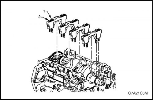
4. Install the crankshaft main bearing caps.
5. Loosely tighten the original inner bolts (1) of the main caps.
Caution! The outer main bearing cap mounting bolts (2) are tightened with dynamic deformation during assembly and must be replaced before reassembly. The outer main bearing cap mounting bolts that are not replaced cannot be tightened to the correct clamping force, which may cause serious engine damage.
6. Loosely tighten the new outer main bearing cap bolts (2).
7. Use a soft-faced hammer to lightly tap the caps into place.
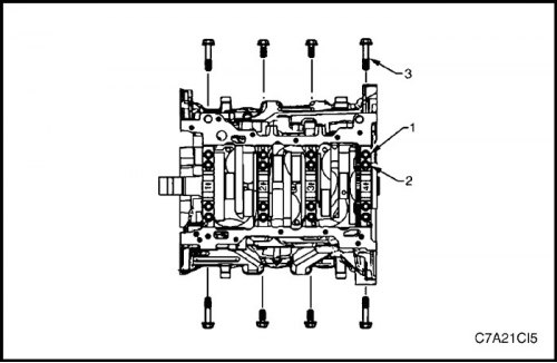
Caution! The short/inner side main bearing cap bolts originally have sealant on the bolt head flange. New bolts must be used. If new bolts are not used, oil may leak from the crankcase past the bolts.
8. Loosely tighten the new short/inner side main bearing cap bolts (4).
Caution! The long/outer side main bearing cap bolts originally have sealant on the bolt head flange. New bolts must be used. If new bolts are not used, oil may leak from the crankcase past the bolts.
9. Loosely install the new long/outer side main bearing cap bolts (3).
10. Tighten the main cap bolts.
Tighten
Tighten the crankshaft main bearing cap inner mounting bolt to 20 N·m (15 ft·lbs), plus another 80°.
Tighten the outer mounting bolt of the crankshaft main bearing cap to 15 N·m (11 ft·lbs), plus another 110°.
Tighten the crankshaft main bearing cap side mounting bolt to 30 N·m (22 ft·lbs), plus another 60°.
11. Make sure the crankshaft rotates without binding or noise.
12. Install the remaining components in the reverse order of removal, see the appropriate section.