


Disassembly
1. Remove the screw (1) securing the oil nozzle (2) (three places).
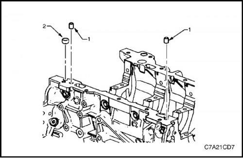
2. Remove the pins (1) for installing the oil pan on the cylinder block and the front expansion plug (2) of the oil channel of the cylinder block of bank 1.
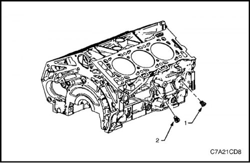
3. Remove the side threaded plug (1) of the oil channel of the cylinder block of bank 1 and the threaded plug (2) of the drain hole for the coolant.
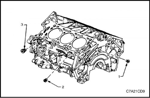
4. Remove the rear threaded plug (1) of the oil channel, the side threaded plug (2) of the coolant drain hole of cylinder bank 2 and the left-hand side threaded plug (3) of the oil channel.
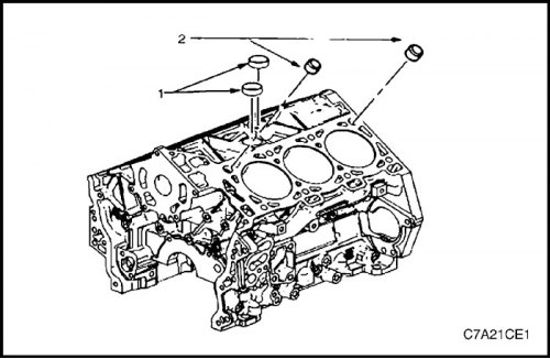
Caution: When removing the coolant expansion plugs, do not apply downward force to avoid damaging the cylinder block.
5. Remove the coolant expansion plugs (1) and the pins (2) for installing the cylinder head on the cylinder block.
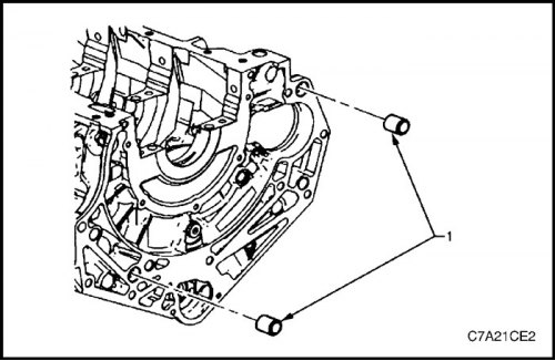
6. Remove the pins (1) for installing the gearbox on the cylinder block.
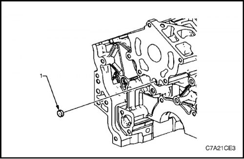
7. Remove the front expansion plug (1) of the oil channel.
Clear
1. Remove all thread sealant, material and gasket sealant using a standard wooden or plastic scraper.
2. Clean all areas listed below with a suitable solvent:
- Sealing surfaces
- coolant channels,
- oil channels,
- bearing supports.
3. Clean all threaded and through holes with a suitable solvent.
4. Dry the cylinder block with compressed air.
Inspection
Measuring cylinder diameters
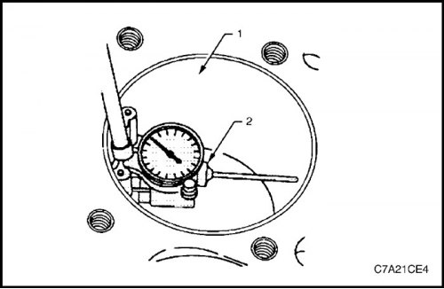
1. Measure the cylinder diameter at a distance of 37 mm from the top plane of the block (1) using a standard bore gauge or the J-8087 tool (2).
2. Record the results and compare with the dimensions specified in the technical specifications.
Note: If the cylinder diameter is larger than that specified in the technical specifications, the cylinder can be bored by 0.25 mm. Only one repair size of pistons and rings is provided for maintenance. If the cylinder diameter exceeds the required value by more than 0.25 mm, the cylinder block must be replaced.
Measuring the taper of cylinders
1. Take measurements on the lateral force bearing surfaces perpendicular to the crankshaft axis, 10 mm below the top surface of the cylinder block, and record the result.
2. Take measurements on the lateral force-bearing surfaces perpendicular to the crankshaft axis, 100 mm below the top surface of the cylinder block, and record the result.
3. Determine the difference between these two measurements. This result will be the taper of the cylinder.
4. Compare the results with the dimensions given in the technical specifications.
5. If the cylinder diameter is larger than that specified in the technical specifications, the cylinder can be bored by 0.25 mm. Only one repair size of pistons and rings is provided for maintenance. If the cylinder diameter exceeds the required value by more than 0.25 mm, the cylinder block must be replaced.
Measuring the out-of-roundness of cylinders
1. Measure the cylinder diameter on the surfaces that bear and do not bear the lateral load, 10 mm below the top surface of the cylinder block. Record the measurement results.
2. Determine the difference between these two measurements. The result will indicate the out-of-roundness of the top end of the cylinder.
3. Measure the cylinder diameter on the surfaces that bear and do not bear the lateral load, 100 mm below the top surface of the cylinder block. Record the measurement results.
4. Determine the difference between these two measurements. The result will indicate the out-of-roundness of the lower end of the cylinder.
5. Compare the obtained results with the dimensions specified in the technical specifications.
6. If the cylinder diameter is larger than that specified in the technical specifications, the cylinder can be bored by 0.25 mm. Only one repair size of pistons and rings is provided for maintenance. If the cylinder diameter exceeds the required value by more than 0.25 mm, the cylinder block must be replaced.
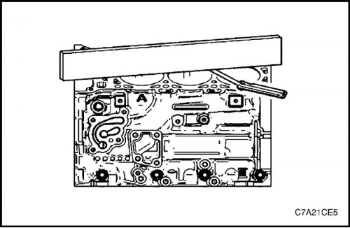
Checking the flatness of the upper surface of the cylinder block
1. The top surfaces of the cylinder block must be clean and free of gasket material.
2. Inspect the surface for any defects or scratches that may interfere with the gasket seal when installing the cylinder head.
3. Place a ruler diagonally across the top face of the cylinder block.
4. Measure the gap between the ruler and the face of the cylinder block at 4 points along the ruler using a gap gauge.
5. If the warpage is less than 0.05 mm, then mechanical treatment of the upper surface of the cylinder block is not required.
6. If the warpage is within the range of 0.05 ±0.20 mm or there are any defects or scratches that may interfere with the gasket seal when installing the cylinder head, the top surface of the cylinder block must be ground.
7. If grinding is required, the maximum permissible thickness of the layer to be removed is 0.25 mm.
8. If it is necessary to remove material more than 0.25 mm thick from the top surface of the cylinder block, the block must be replaced.
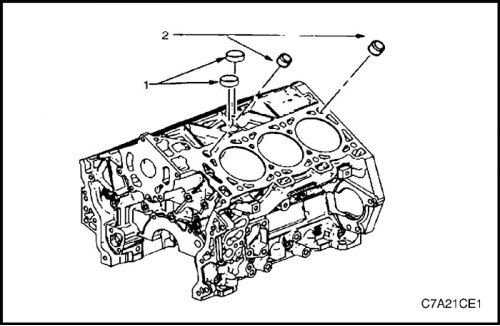
Assembly
1. Apply RTV sealant to new coolant expansion plugs (1) and install them in place.
2. Install the pins (2) to install the cylinder head onto the cylinder block.
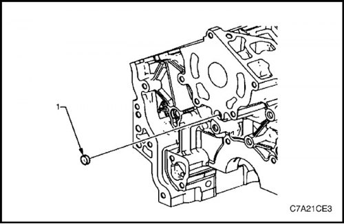
3. Install a new front oil channel expansion plug (1).
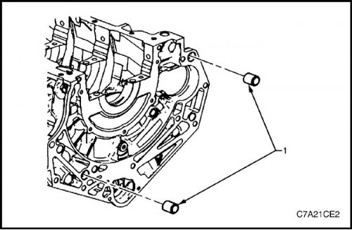
4. Install the pins (1) to install the gearbox onto the cylinder block.
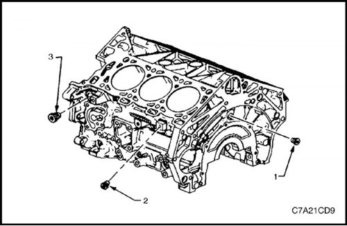
5. Install the rear threaded plug (1) of the oil channel, the side threaded plug (2) of the coolant drain hole of cylinder bank 2 and the left-hand side threaded plug (3) of the oil channel.
Tighten
Tighten the rear cylinder block oil passage plug to 31 N·m (33 lb-ft).
Tighten the bank 2 cylinder block coolant passage side thread plug to 31 N·m (23 lb-ft).
Tighten the bank 2 cylinder block oil passage side thread plug to 31 N·m (23 lb-ft).
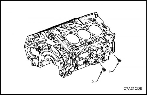
6. Install the threaded plug (1) of the oil channel and the threaded plug (2) of the coolant channel on the right side.
Tighten
Tighten the bank 1 cylinder block oil passage side thread plug to 31 N·m (23 lb-ft).
Tighten the bank 1 cylinder block coolant passage side thread plug to 31 N·m (23 lb-ft).
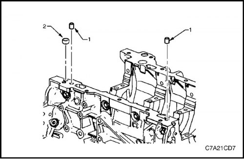
7. Install a new expansion plug (1) of the oil passage on the front bearing surface of the oil pan, on the bank 1 side, and pins (2) for installing the oil pan on the cylinder block.
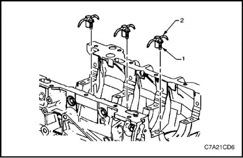
8. Install (three places) the oil nozzle (2).
9. Install (three places) the screw (1) securing the oil nozzle.
Tighten
Tighten the oil nozzle retaining screw to 10 N·m (89 lb-in).
[The article was reprinted from the website: «ChevyMan.ru»]