Contents: Removal procedure ↧ Disassembly ↧ Verification procedure ↧ Assembly ↧ Installation procedure ↧
Removal procedure
1. Remove the engine assembly. Follow step "Engine assembly" in this section.
2. Remove both cylinder heads as an assembly. See "Cylinder head block" in this section.
3. Remove the oil pan assembly. See "Oil pan" and "Oil pump suction pipe assembly" in this section.
4. Mark the top of the piston to be removed, indicating which cylinder it is located in.
5. Install the EN-46111 tool (1) on the crankshaft (2).
6. Turn the crankshaft so that the piston being removed is at the bottom of its stroke - at bottom dead center (BDC).
Attention! If the connecting rod bearings were used on a running engine, they must be replaced with new ones during subsequent assembly.
7. Before removing the connecting rods, check the connecting rod side clearance by following the steps below.
A. Using light blows from a wooden or other soft hammer, move the connecting rod along the crankshaft journal to the end.
B. Using feeler gauges, measure the clearance between the crankshaft counterweight and the connecting rod.
C. The connecting rod side clearance should not exceed the value specified in the specifications.
D. If the axial clearance exceeds the required value, measure the width of the big end of the connecting rod.
E. If the width of the big end of the connecting rod is significantly less than the required value, and the side surface of the connecting rod is badly worn, replace the connecting rod.
F. If the connecting rod width is within specifications and there are many scratches on the connecting rod journals, replace the crankshaft.
Caution! Do not use a stamp, punch or any other tool that could damage or stress the connecting rod and connecting rod cap. A deformed or stressed connecting rod could cause significant engine damage.
8. Use a felt-tip pen to write the cylinder number on the connecting rod and on the connecting rod head cover.
Caution! Connecting rod bolts made of powdered metal are plastically deformed when tightened to the required torque. If these bolts are loose or removed, they must be replaced. If the connecting rod bolts are not replaced, they will not be able to be tightened to the required torque, which may lead to serious engine damage.
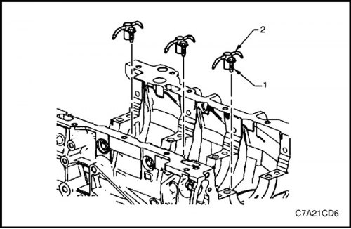
9. Remove the connecting rod bolts (1), loosening them gradually and one by one.
Caution! Connecting rod head caps must be used without transferring them to other connecting rods.
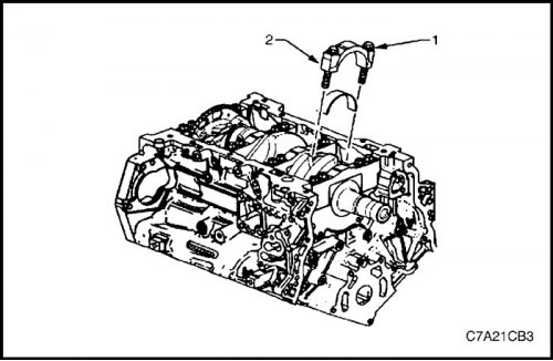
10. Remove the connecting rod head cover (2).
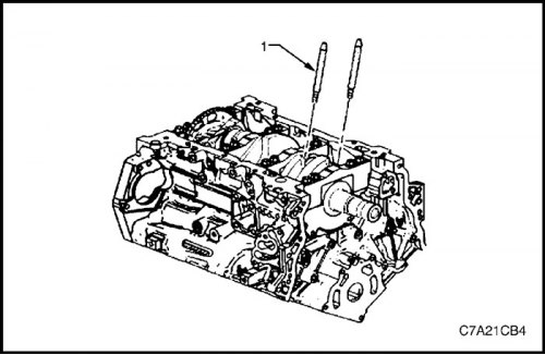
11. Install the EN-46121 guide kit (1) for the connecting rod into the bolt holes.
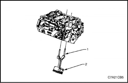
Caution! When removing the connecting rod and piston assembly, care must be taken not to damage the crankshaft journal, cylinder wall, or piston cooling nozzles.
12. Using the EN-46121 guide kit (1), push the connecting rod and piston assembly (2) out through the top of the cylinder.
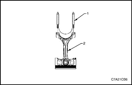
Attention! When disassembling, it is necessary to maintain the original location of the connecting rod, connecting rod head cover, piston and bearings. This will also help in diagnosing the condition of the mechanical part of the engine.
13. Remove the EN-46121 guide kit (1) for the connecting rod from the bolt holes.
14. Remove the upper bearing shell of the big end of the connecting rod (2).
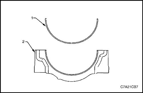
15. Remove the lower bearing shell (1) of the cap (2) of the big end of the connecting rod.
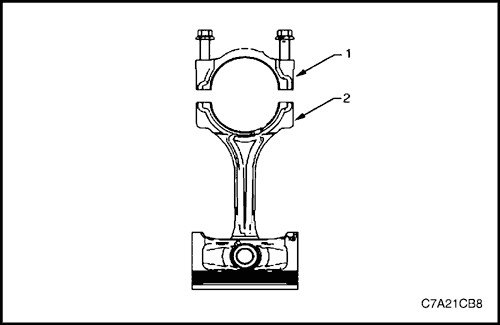
16. Install the connecting rod cap (1) onto the connecting rod (2) to avoid damaging their mating surfaces.
Note: The cap and connecting rod are a match and must be stored together.
17. Repeat operations 4 through 16 for the remaining connecting rod and piston groups.
Disassembly
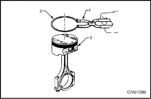
Attention! To remove and install piston rings, use special pliers. When installing, the rings must be spread apart just enough to be able to pass the piston bridge between the piston grooves. If the rings are spread apart too much, the top ring will be destroyed and the others will be deformed.
1. Using pliers (1), remove the piston rings (2). Store each ring in a clean cloth.
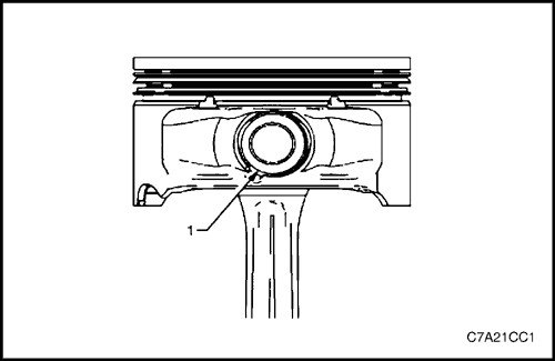
Caution! Reuse of piston pin retainers is not permitted.
2. Remove the piston pin retainers using the notch (1) on the side of the piston. Discard the piston pin retainers.
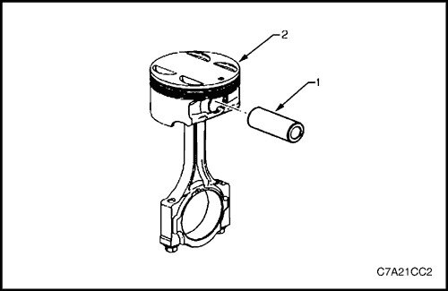
3. Pull the piston pin (1) out of the piston (2). The piston will separate from the connecting rod.
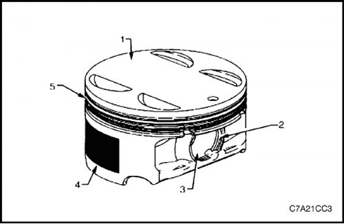
Verification procedure
1. Inspect the pistons for the following faults.
- Are there any eroded areas on the piston bottom (1)?.
- Are there any joints in the grooves for the piston pin retainers (2)?.
- Are the piston pin holes and piston pins (3) worn out?.
- Is the piston skirt coating (4) scratched or damaged?.
- Are the ring grooves cracked, dented or scored which could cause seizure (5).
- Are the bridges between the piston ring grooves warped or worn out?
2. Replace pistons that show any signs of damage or excessive wear.
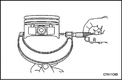
3. Measure the piston width using the following procedure.
- Using an outside micrometer, measure the piston width on the piston bearing surface, perpendicular to the piston pin centerline.
- Compare the piston measurement result with its size in the original cylinder, subtracting the piston width from the cylinder diameter.
- If the clearance obtained as a result of measurement is greater than the standard, and the cylinder bore is within the standard, it is necessary to replace the piston.
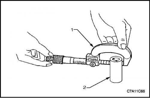
4. Measure the clearances between the piston pin bore and the piston pin (2) using the following procedure.
- There should be no carbon deposits or scoring in the piston pin holes or on the pins.
- To measure the piston pins in the areas of contact surface with the pistons, use an external micrometer (1).
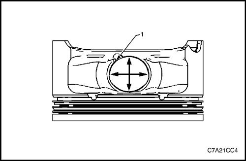
- Using an inside micrometer, measure the piston pin bore (1). Compare the result with the piston pin diameter and the clearance between the piston pin and the piston pin bore. Follow step "Engine Specifications" in this section.
- If the gap is too large, determine which part does not meet the standard and replace it if necessary.
- Replace the piston if any of its dimensions are not within specification.
- If the new piston does not meet the standard clearance, the cylinder can be bored by 0.25 mm. Only one repair size of pistons and rings is provided for maintenance.
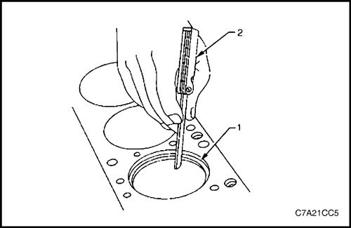
5. Measure the piston ring end clearance using the following procedure.
- There should be no carbon deposits or scoring in the piston pin holes or on the pins.
- Place the piston ring (1) in the bore in which it will move, approximately 25 mm below the surface of the cylinder block plate. Make sure that the ring is installed at right angles to the cylinder bore by setting the position of the ring using the piston head.
- Measure the piston ring end clearance using clearance gauges (2).
- If the gap exceeds the specified standards, the piston rings must be replaced.
- Repeat the procedure for all piston rings.
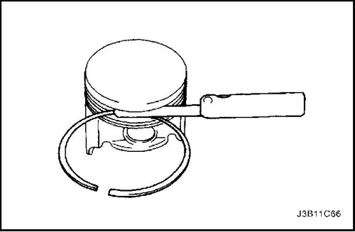
6. Measure the piston ring side clearance using the following procedure.
- Insert the piston ring completely into the piston groove. If the ring is seized by the piston groove, file the groove with a fine file. If the ring is seized by deformation of the piston ring, the ring must be replaced.
- After installing the piston ring on the piston, check the gaps in several places using feeler gauges.
- Compare the measurements with the piston ring side clearance. Follow step "Engine Specifications" in this section.
- If the gap is greater than specified in the standards, it is necessary to replace the piston rings.
- If the new ring does not reduce the gap and achieve the standard, then a new piston must be installed.
- If the new piston fails to achieve the standard clearance, the cylinder block size must be increased by 0.25 mm. There is only one oversize piston and ring available for service.
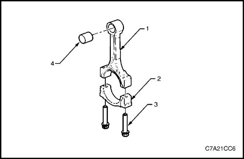
7. Check the connecting rods as follows.
- Inspect the piston pin bushing (4) for scratches or damage.
- Check that the connecting rod (1) is not twisted or bent.
- Check the connecting rod cover (2) for dents or damage due to possible interference.
- Check the connecting rod bearing support surface for scratches or wear marks.
- If there are minor scratches and abrasion marks on the connecting rod holes, the holes should be cleaned around the circumference using fine sandpaper.
- Temporarily install the old bolts (3). They must be replaced during final installation.
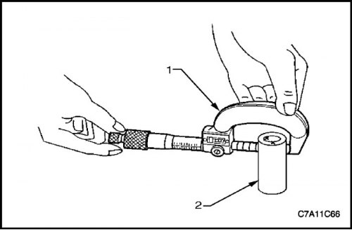
8. Measure the clearance between the connecting rod piston pin bore and the piston pin using the following procedures.
- Using an external micrometer (1), take two measurements of the piston pin (2) in the connecting rod contact area.
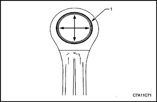
- Using an inside micrometer, measure the piston pin bore of the connecting rod (1).
- Subtract the piston pin diameter from the piston pin bore size.
- Compare gap measurements. Follow step "Engine Specifications" in this section.
- If the clearance is too large, replace the piston pin. If a new pin does not solve the clearance problem, the connecting rod will need to be replaced.
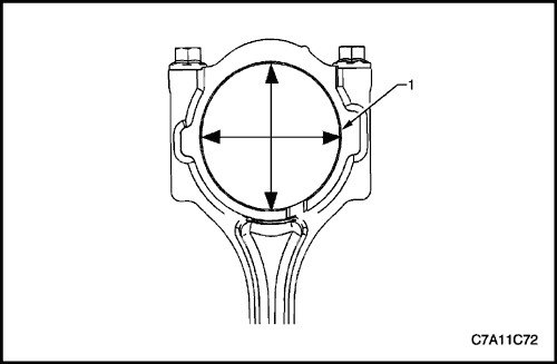
9. Measure the connecting rod main bearing bore (1) using the following procedures.
- Using an inside micrometer, measure the connecting rod main bearing bore.
- Compare the hole measurements. Follow the step "Engine Specifications" in this section.
- If the hole does not match the standard, replace the connecting rod. Do not repair the connecting rod.
10. Check the cylinder block plate surface for flatness using a straightedge and feeler gauge. Follow step "Engine Specifications" in this section.
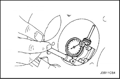
11. Check the bearing bore for concentricity and alignment using the J-8087 Cylinder Bore Gauge, Follow step "Engine Specifications" in this section. If the bearing bore is outside the normal range, replace the cylinder block.
12. Check the cylinder block bore for wear, runout and taper using a bore gauge. Follow step "Engine Specifications" in this section.
13. Check the cylinder block bore polish. Lightly hone the cylinder bore if necessary.
Assembly
Piston and piston pin
Caution! The arrow on the piston bottom must point towards the front of the engine.
Note: There is no specific direction for the connecting rod and it can be connected to the piston in any orientation.
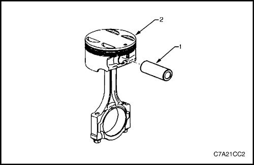
1. Lubricate the piston pin holes (1) in the piston (2) and connecting rod with clean engine oil.
2. Connect the piston to the connecting rod using the piston pin. When reusing the marked connecting rod, the piston must be correctly oriented.
3. Align the piston pin holes in the piston and connecting rod.
4. Insert the piston pin into the piston and connecting rod.
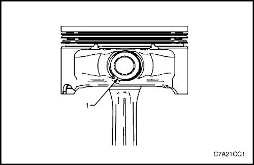
Caution! New piston pin retainers must be used. Reusing piston pin retainers is not permitted.
5. Install new piston pin retainers (1).
6. It is necessary that the piston pin retainers are fully seated in the grooves.
7. Repeat operations 1 through 6 for the remaining pistons.
Piston ring
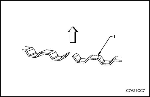
1. Before installation, it is necessary to correctly orient the expander (1) of the oil scraper rings. The ends of the expander should be directed towards the piston bottom.
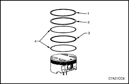
2. Using piston ring pliers, install the oil scraper rings according to the following instructions:
a. Install the expansion ring (3).
b. Install the upper and lower discs (4) of the oil scraper ring. Spread the ring just enough to pass the piston diameter. Spreading the piston rings too much will cause them to deform or break.
3. Install the second (2) and upper (1) piston rings in the following order:
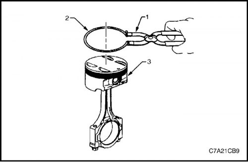
4. Using pliers (1), install the second piston ring (2) onto the piston (3). Do not spread the ring too much. Repeat this operation for the upper ring.
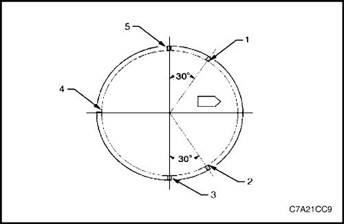
5. After installing the rings, position the ring locks as follows. Use the arrow on the piston as a reference line.
- Position of the lower oil scraper ring (1).
- Position of the upper oil scraper ring (2).
- Position of the upper ring (3).
- Position of the oil scraper ring expander (4).
- Position of the second ring (5).
Connecting rod bearing
Attention! If the connecting rod bearings were used on a running engine, they must be replaced with new ones during subsequent assembly.
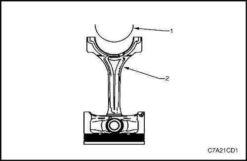
1. Wipe the bearing shell hole in the connecting rod (2) and connecting rod cap with a lint-free, thread-free cloth.
2. Clean the lower connecting rod head bearing shells from oil.
3. Install the new upper bearing shell (1) in place. Turn the shell so that its tab is located in the groove of the connecting rod. The shell should be located in the connecting rod without protruding outward.
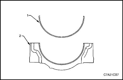
4. Install the lower bearing shell (1) onto the connecting rod cover (2).
5. Turn the bearing so that its tab is located in the groove of the connecting rod. The bearing should be located in the connecting rod cap without protruding outward.
Installation procedure
Installing a connecting rod with a connecting rod bearing
1. Generously lubricate the cylinder bore, piston rings and piston skirt with engine oil.
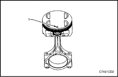
Caution! The piston has a specific orientation that must be ensured when installing it into the cylinder block. The arrow on the bottom of each piston must point toward the front of the engine.
2. For a cylinder, it is necessary to use only the connecting rod and piston group having the same number as the cylinder. The correct orientation is indicated by the point (1) on the bottom of the cylinder.
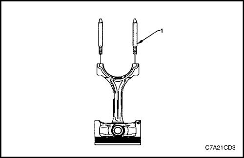
3. Install the EN-46121 guide kit (1) for the connecting rod into the bolt holes.
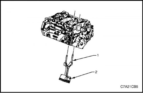
4. Compress the piston rings using a standard mandrel.
Caution! When installing the connecting rod and piston group, extreme caution is required to avoid damaging the cylinder bore, oil supply nozzles or crankshaft surfaces.
5. Slowly insert the piston (2) and connecting rod assembly into the cylinder, holding them with one hand on the top of the cylinder and with the other on the bottom. Contact of the connecting rod with the cylinder bore is not allowed.
6. When the piston ring mandrel rests against the cylinder block surface, insert the piston into the cylinder, tapping it lightly with a soft hammer handle. Using EN-46121 guide pins (1), guide the connecting rod onto the crankshaft journal, while lightly tapping the piston along the cylinder with a soft hammer.
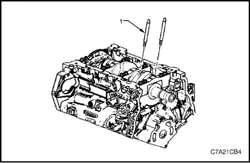
7. Remove the EN-46121 guide kit (1) for the connecting rod from the bolt holes.
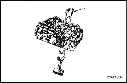
Measuring the clearance in the connecting rod bearing
Note: New connecting rod bearing clearances must be checked before final assembly.
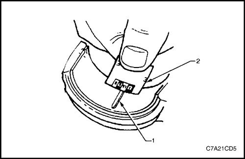
1. Place a piece of new calibrated plastic wire, at room temperature, along the entire length of the crankpin.
2. Install the connecting rod bearing into the connecting rod cap.
3. Install the connecting rod cap (1) onto the connecting rod and ensure that the bearing shell tabs are positioned on one side of the connecting rod.
Note: It is permissible to use the old connecting rod bolts to measure the connecting rod bearing clearance.
4. Install the connecting rod cap bolts.
Tighten
Tighten the bolts to 30 N·m (22 lb-ft), then loosen the bolts completely. Tighten the connecting rod cap bolts to 25 N·m (18 lb-ft), and turn the bolts another 110° using the angular torque gauge KM-470-B.
5. Leave the assembly in this state for at least 2 minutes.
6. Remove the connecting rod cap bolts and discard them.
7. Remove the connecting rod cover.
8. Determine the clearance in the connecting rod bearing by comparing the width of the flattened plastic wire (1) at its widest point with the scale on the package of calibrated wire (2).
9. Compare the measurement result with the technical specifications.
10. If the new bearings do not provide the required clearance with the crankshaft, check the following:
- a. Measure the crankshaft journals to determine if they are the correct size and ensure that the correct new bearings are used. If the crankshaft journals are not the correct size, replace or regrind the crankshaft. Machining of the crankshaft is permitted and bearings of repair sizes are available for this purpose.
- b. Measure the diameter of the bearing bore in the connecting rod to ensure that it is the correct size. The connecting rod is not machined and must be replaced if it is not within specification.
11. Clean the crank pins of plastic wire using a lint-free, thread-free cloth.
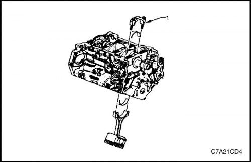
Final connecting rod installation procedure
1. Carefully move the connecting rod away from the crankshaft journal slightly to lubricate the surface of the crankshaft journal that the connecting rod bearing contacts.
2. Generously lubricate the surface of the crankshaft connecting rod journal where the connecting rod bearing contacts with clean engine oil.
3. Place the connecting rod on the crankshaft journal.
4. Install the connecting rod cap (1) onto the connecting rod and ensure that the bearing shell tabs are positioned on one side of the connecting rod.
Attention!
- Do not lubricate new connecting rod cap bolts. New bolts are already lubricated with graphite grease. Lubricating the connecting rod bolts will cause internal hydraulic pressure to build up when the bolts are tightened to the specified torque. Unintended hydraulic pressure may cause component failure and significant engine damage.
- Do not use old connecting rod cap bolts.
5. Install new connecting rod cap bolts.
Tighten
Tighten the bolts to 30 N·m (22 lb-ft), then loosen the bolts completely. Tighten the connecting rod cap bolts to 25 N·m (18 lb-ft), and turn the bolts another 110° using the angular torque gauge KM-470-B.
Note: During and after installation, ensure that the pistons are correctly positioned and oriented in the cylinders. The arrow on the bottom of each piston should point toward the front of the engine.
6. Repeat the described operations for the remaining connecting rod and piston groups.
7. Install the oil pan and oil pump oil suction tubes. See "Oil pan" and "Oil pump suction pipe assembly" in this section.
8. Install the cylinder heads. See "Cylinder head block" in this section.
9. Install the engine assembly. Follow step "Engine assembly" in this section.