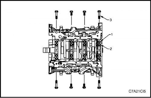
Cylinder head and valve train parts
Disassembly
Caution: Make sure the valve heads do not come into contact with anything during the following operation to avoid bending or damage.
1. Remove the cylinder head assembly. See "Cylinder head block" in this section.
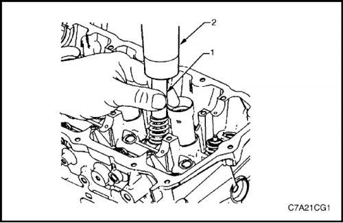
2. Using a properly sized deep chuck (1) and a plastic hammer (2), lightly tap the valve spring retainer to loosen the valve spring cotters.
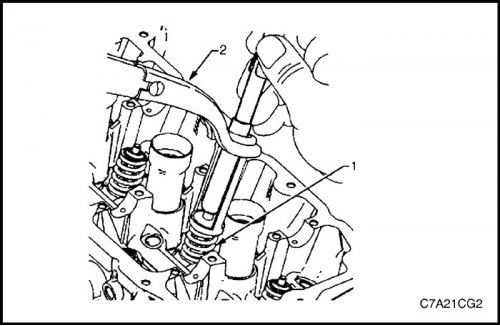
Compressed valve springs (1) are under high tension with respect to the valve spring compressor (2). Valve springs that are not properly compressed by the valve spring compressor or released from it may fly out of the valve spring compressor with considerable force. Use caution when compressing or releasing a valve spring with the valve spring compressor and when removing or installing valve stem keys. Failure to exercise caution may result in personal injury.
Caution: Do not compress the valve spring to less than 24.0 mm. Contact between the valve spring retainer and the valve stem seal may result in potential damage to the valve stem seal.
3. Compress the valve spring (1) using the valve spring compressor, tool no. J-8062 (2), and the adapter, tool no. EN-46119.
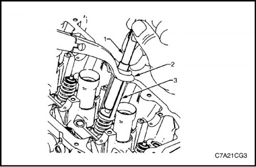
4. Remove the valve cotters using tool EN-46117 (1).
5. Remove the valve spring compressor (2) and adapter (3).
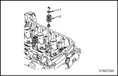
6. Remove the valve spring retainer (1).
7. Remove the valve spring (2).
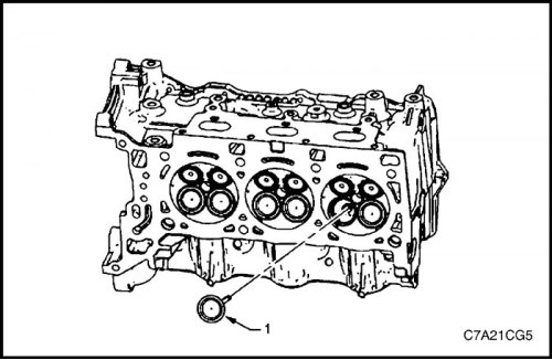
8. Remove the valves (1).
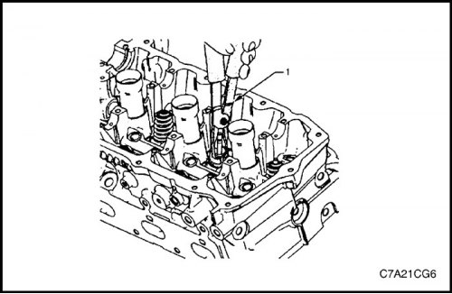
Caution: Never reuse the valve stem seal.
9. Remove the valve stem seal using tool #EN-46116 and discard.
10. Repeat these operations for the remaining valves.
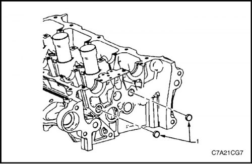
11. Remove the expansion plugs (1) from the cylinder head oil line.
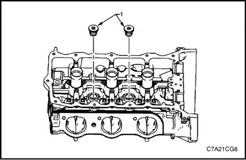
12. Remove the threaded plugs (1) of the cylinder head coolant.
Clear
Caution! Wire brushes and steel scrapers should not be used during the cleaning process due to the aluminum alloy in the cylinder head construction, as this may damage the sealing surfaces. Alternatively, use a wooden or plastic scraper.
1. Remove old thread sealant, gasket material and caulk with a regular plastic or wooden scraper.
2. Clean all cylinder head surfaces with a non-rusting solvent.
3. Blow out all oil lines with compressed air.
4. Remove all carbon deposits from the combustion chambers.
5. Clean all tappet pockets from deposits and scale.
Examination
Inspection
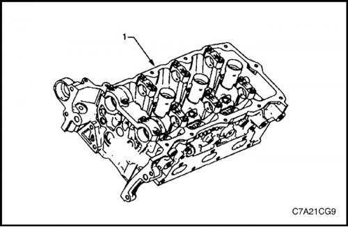
1. Check the camshaft bearing surfaces in the cylinder head (1) for the following conditions:
- excessive surface scoring or chipping;
- color change from overheating, and
- deformation from excessive wear.
2. If any of the above conditions are present on the camshaft bearing surfaces, replace the cylinder head. Do not machine the camshaft bearing journals.
3. Check the cylinder head for the following conditions:
- cracks, damage or chipping of the surface in the combustion chambers;
- dirt in the oil lines. Continue cleaning the lines until all dirt is removed;
- coolant leaks or damage to the sealing surface of the upper face. If there are coolant leaks, measure the deformation of the surface;
- unevenness or any other defects that could reduce the sealing properties of the new secondary camshaft chain tensioner gasket. Replace the cylinder head. Do not machine the camshaft bearing journals.
- damage to any surface of the gasket;
- damage to the threaded holes of any of the bolts;
- burnt or eroded areas in the combustion chamber;
- cracks in the intake ports and combustion chambers;
- external cracks in water channels;
- restrictions in the inlet or outlet ducts;
- restrictions of cooling system flows;
- rusty, damaged or leaking plugs.
4. If cracks or damage are found on the cylinder head, it must be replaced. It is not recommended to carry out welding work on the cylinder head or repair damage.
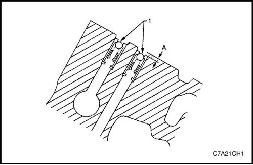
5. Check the camshaft position changer oil supply shut-off valves (1) and ensure that they are correctly positioned in the cylinder head. The camshaft position changer oil supply shut-off valve should be recessed 2 mm below the top surface (A) of the cylinder head.
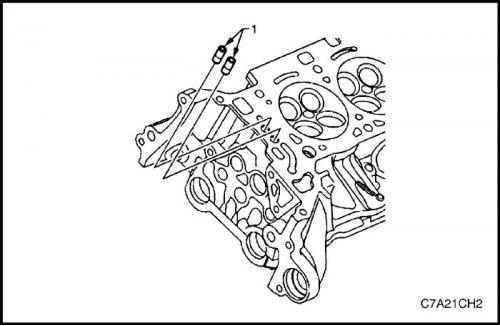
6. Damaged, clogged or blocked check valves (1) can be replaced using the camshaft position actuator check ball valve remover and installer, tool no. EN-46122.
Cylinder head measurement
Camshaft journal clearance
1. Install the camshaft bearing cap into the cylinder head without the camshaft.
2. Install the camshaft cover mounting bolts and tighten the bolts to 10 N·m (89 lbs.in).
3. Measure the camshaft bearings with an inside micrometer.
4. Subtract the camshaft journal diameter from the camshaft bearing diameter. This gives the running clearance. If the running clearance exceeds specifications and the camshaft journals are within specifications, replace the cylinder head.
Camshaft journal alignment
1. Check the camshaft bearing surfaces in the cylinder head for any defects or scratches that could prevent the camshaft from achieving the correct clearances. Repair any minor defects or scratches.
2. Install the camshafts into the cylinder head.
3. Install the camshaft bearing caps.
4. Install the camshaft cover mounting bolts and tighten the bolts to 10 N·m (89 lbs.in).
5. Make sure the camshafts rotate freely in the cylinder head. If the camshaft does not rotate freely, replace the cylinder head.
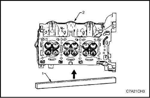
Checking the flatness of the top surface
1. Make sure the top surfaces of the cylinder head are clean and free of gasket material.
2. Check the surface for any defects or scratches that might prevent the cylinder head gasket from sealing properly.
3. Place the ruler (1) diagonally parallel to the front surface of the upper plane of the cylinder head (2).
4. Measure the gap between the straightedge and the face of the cylinder head at four points along the straightedge using a gap gauge.
5. If the deformation is less than 0.05 mm, then restoration of the surface of the upper plane of the cylinder head is not required.
6. If the deformation is in the range of 0.05±0.20 mm or there are defects or scratches that could prevent the cylinder head gasket from sealing properly, the surface of the upper plane of the cylinder head must be restored.
7. If surface restoration is required, the maximum amount that can be removed is 0.25 mm.
8. If more than 0.25 mm of material needs to be removed from the surface of the upper plane of the cylinder head, the head must be replaced.
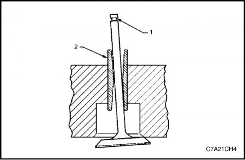
Measuring the valve guide bushing
1. Measure the clearance between the valve stem (1) and the guide bushing (2). Excessive clearance between the valve stem and the guide bushing may cause excessive oil consumption and may also lead to valve failure. Insufficient clearance will result in increased noise and sticking during valve operation and will disrupt the smooth operation of the engine assembly.
2. Attach a dial indicator to the cylinder head by the edge of the camshaft cover.
3. Position the dial indicator so that the movement of the valve stem from side to side, across the cylinder head, causes the dial indicator rod to move straight. The dial indicator rod should contact the surface of the valve stem just above the valve guide.
4. Lower the valve head approximately 0.064 mm from the valve seat.
5. Applying light pressure, move the valve stem from side to side to obtain clearance readings.
- If the valve clearance exceeds the specified value and a new standard diameter valve stem does not bring the clearance to specification, the valve guide size can be increased by 0.075 mm using the Valve Guide Reamer Tool No. J 42096, or by 0.375 mm using the Valve Guide Reamer Tool No. EN-46120. There are two sizes of overhaul valve stems.
- Wear of 10 mm on the bottom of the valve guide bushing is not significant enough to affect normal operation.
- If increasing the guide bushing size does not bring the clearance to specifications, replace the cylinder head.
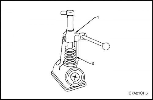
Checking and measuring the valve spring
1. Measure the clearance between the valve stem (1) and the guide bushing (2). Excessive clearance between the valve stem and the guide bushing may cause excessive oil consumption and may also lead to valve failure. Insufficient clearance will result in increased noise and sticking during valve operation and will disrupt the smooth operation of the engine assembly.
2. Attach a dial indicator to the cylinder head by the edge of the camshaft cover.
3. Position the dial indicator so that the movement of the valve stem from side to side, across the cylinder head, causes the dial indicator rod to move straight. The dial indicator rod should contact the surface of the valve stem just above the valve guide.
4. Lower the valve head approximately 0.064 mm from the valve seat.
5. Applying light pressure, move the valve stem from side to side to obtain clearance readings.
- If the valve clearance exceeds the specified value and a new standard diameter valve stem does not bring the clearance to specification, the valve guide size can be increased by 0.075 mm using the Valve Guide Reamer Tool No. J 42096, or by 0.375 mm using the Valve Guide Reamer Tool No. EN-46120. There are two sizes of overhaul valve stems.
- Wear of 10 mm on the bottom of the valve guide bushing is not significant enough to affect normal operation.
- If increasing the guide bushing size does not bring the clearance to specifications, replace the cylinder head.
Examination
1. Clean the valve springs in solvent.
2. Dry the valve springs with compressed air.
3. Check the valve springs for broken coils or coil ends.
Measurement
1. Use a standard valve spring tester to measure valve spring tension.
Attention! Do not use adjustment pads to increase the spring load. The use of adjustment gaskets can cause the valve spring to reach its lower limit before the camshaft cam reaches its peak lift.
2. If a decrease in valve spring load is detected, replace the valve springs.
Lapping the valve and seat
Cleaning the valve
Caution! Do not use a wire brush on any part of the valve stem. The valve stem is chrome plated for increased wear resistance. Wire brushing the stem could remove the chrome plating.
1. To clean carbon build-up from the valve head, use a soft bristle brush.
2. Clean the valve thoroughly with solvent and wipe dry.
Inspection of the valve
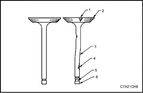
1. Check for valve damage from head to stop as follows.
- Is there any surface chipping in the valve seat area (1)
- Is the valve edge (2) the correct shape?
- Is there a bend in the valve stem (3)
- Is there any surface chipping or excessive wear in the piston rod (4)
- Are the valve key grooves (5) worn out?
- Is the valve stop (6) worn out?.
2. Replace the valve if any of these signs occur.
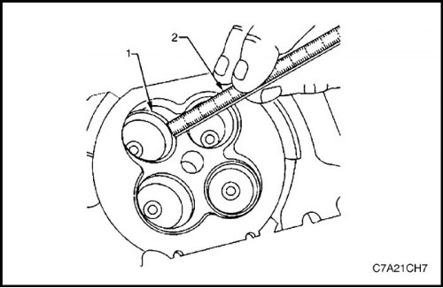
Measuring valve seat width
1. Measure the width of the valve seat (1) in the cylinder head using a ruler (2).
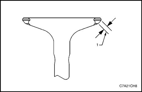
2. Measure the seat width on the valve seat surface (1) using a suitable ruler.
Caution! The contact surface of the seat must be at least 0.5 mm away from the outside diameter (edge) of the valve. If the contact surface is too close to the edge, the seat must be rebuilt to move the contact surface away from the edge.
3. If the seat width is acceptable, check the valve seat for cylindricity.
4. If the seat width is unacceptable, lap the valve seat until the width returns to specification. Proper valve seat width is important to ensure adequate valve heat transfer.
Measuring the cylindricity of the valve seat
1. Measure the valve seat cylindricity using a dial indicator attached to a cone-shaped centering device installed in the guide. The centering device should have a slight bend when installed in the guide.
Caution! The correct size centering device must be used. Do not use centering devices with adjustable diameter. Adjustable centering devices may damage the valve guide.
2. If the valve seat cylindricity exceeds specifications, lap the valve and valve seat.
3. When using new valves, the valve seat cylindricity should be within 0.05 mm.
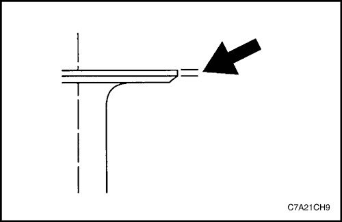
Measuring the valve edge
1. Measure the valve edge using a suitable ruler.
2. If the valve edges are out of specification, replace the valves.
3. If the valve edges are within specifications and do not require regrinding, check the valve seat alignment.
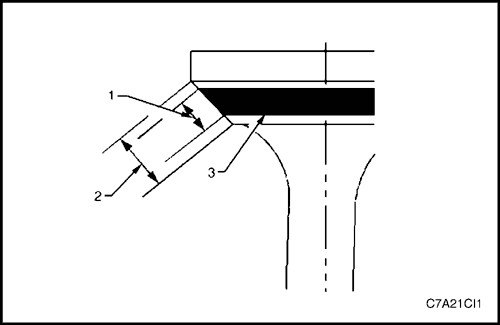
Valve to seat alignment measurement
Checking the valve to seat alignment determines whether the valve and seat are sealed correctly.
Measure the valve seat and valve face to ensure proper valve sealing.
1. Lightly coat the working surface of the valve with blue dye (3).
2. Install the valve into the cylinder head.
3. Turn the valve in the seat with enough pressure to wipe off the dye.
4. Remove the valve from the cylinder head.
5. If the valve seat is concentric, providing a proper seal against the valve stem, then a continuous mark (1) will be made around the entire perimeter of the seat (2).
Caution! The worn mark must be at least 0.5 mm from the edge of the valve. If the mark is too close to the edge, the seat must be rebuilt so that the contact surface moves away from the edge.
6. If the seat is not concentric with the stem, the mark will not be continuous around the entire perimeter of the valve seat. The valve should be reground or replaced, and the seat should be rebuilt.
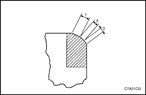
Valve and seat restoration procedure
If the valve seat width, cylindricity or alignment is outside specifications, lap the seats to ensure proper heat transfer and prevent carbon build-up on the seats.
If valve seat reconditioning is required, regrind the valve seating surface unless a new valve is being used.
1. Lapping the valve seats (2) at the correct angle according to specifications.
2. Using the correct angle specifications, lap and profile the valve seat (1) so that the valve seating surface (2) is correctly positioned relative to the valve.
3. Using the correct angle specifications, lap and grind the valve seat (3) to reduce the valve seat width to within specifications.
4. If using the original valve, lap it to specification. Measure the valve edge again after lapping. Replace the valve if the edge is outside specification. New valves do not require lapping.
5. When lapping valves and seats, grind off as little material as possible. Cutting off the valve seat reduces the force of the valve spring.
6. Install the valve into the cylinder head.
Caution! When using reground valves, lap the valves into their seats with a fine grinding compound. After reground and lapping, the restored surfaces should be smooth and correct, requiring as little lapping as possible. Excessive lapping will cause grooves to form on the valve seating surface, which will prevent a secure fit when heated.
Note:
Before final assembly, clean the valve and seat with solvent and compressed air to remove any remaining finishing compound.
Never use valve trim when installing new valves.
7. Once the correct valve seat width has been achieved in the cylinder head, measure the valve stem height.
8. If the valve stem height is acceptable, check the seat alignment.
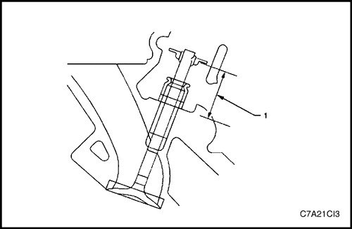
Procedure for measuring valve stem height
Caution: To determine the valve stem height value, measure the distance from the valve spring seat to the valve spring retainer.
1. Install the valve into the valve guide.
2. Make sure the valve is seated in the valve seat.
3. Install the valve stem seal.
4. Install the valve spring retainer and valve stem keys.
5. Measure the distance (1) from the cylinder head to the bottom of the valve spring retainer.
6. If it exceeds the maximum height specified in the specifications, a new valve should be installed and the valve stem height re-measured.
Attention!
Do not sharpen the valve stem stop. The valve stop has been hardened and sharpening the stop will destroy the hardened surface, causing premature wear and possible engine damage.
Do not use washers to adjust the height of the valve stem. The use of adjustment washers will cause the valve spring to reach its lower limit before the camshaft cam reaches its peak lift.
7. If the valve stem height still exceeds the maximum height specified in the specifications, the cylinder head must be replaced.
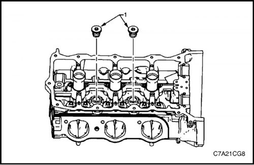
Assembly
1. Install the cylinder head coolant screw plugs (1).
Tighten
Tighten the cylinder head coolant plugs to 31 N·m (23 ft·lbs).
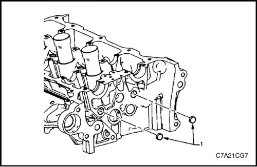
2. Install the expansion plugs (1) of the cylinder head oil line.
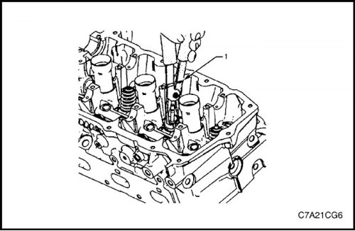
Caution! Never reuse the valve stem seal. Always use new seals when assembling the cylinder head.
3. Install the valve stem seals onto the guide bushings using tool No. EN-46116 (1).
Caution: During installation, force should only be applied to the surface of the valve stem seal that contacts the valve spring.
4. Using the tool no. EN-46116, press and screw the valve stem gland into its original position on the valve guide sleeve until the seal definitely engages the guide sleeve.
5. Lubricate the valve stem and the inside diameter of the valve guide with clean engine oil.
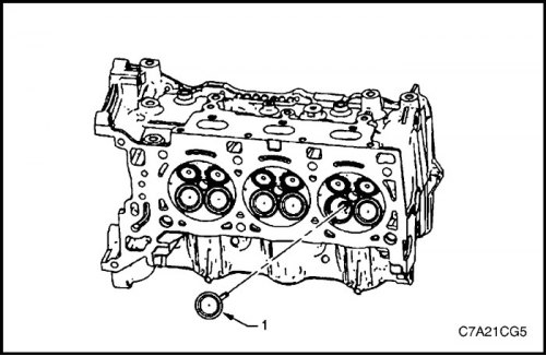
Caution! When installing the valve (1), the valve stem seal must not separate from the valve guide sleeve.
6. Insert the valve into the valve guide until it rests against the valve seat.
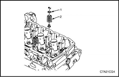
7. Place the valve spring (2) into the spring support cup (1).
8. Place the valve spring retainer on the valve spring.
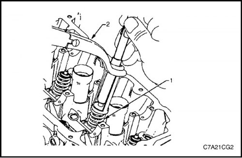
Compressed valve springs (1) are under high tension with respect to the valve spring compressor (2). Valve springs that are not properly compressed by the valve spring compressor or released from it may fly out of the valve spring compressor with considerable force. Use caution when compressing or releasing a valve spring with the valve spring compressor and when removing or installing valve stem keys. Failure to exercise caution may result in personal injury.
Caution: Do not compress the valve spring to less than 24.0 mm. Contact between the valve spring retainer and the valve stem seal may result in potential damage to the valve stem seal.
9. Compress the valve spring using the valve spring compressor, tool no. J-8062, and the adapter, tool no. EN-46119.
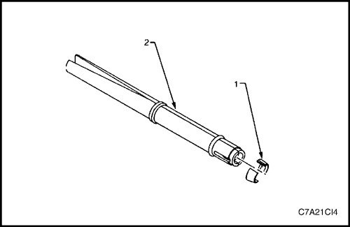
Caution! Ensure that the valve keepers (1) are correctly positioned in tool no. EN-46117 (2). The valve keepers must be installed with the tapered end facing the valve stem seal.
10. With the spring compressed, install the valve cotters into tool no. EN 46117.
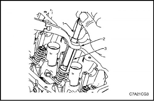
11. Set the crackers to their original position by pressing the tool (1) down and releasing the tension of the valve spring compressor (2).
12. Ensure that the valve keepers are installed correctly by placing a rag over the valve stop and tapping it lightly with a hammer without rebound. The valve keepers and spring should remain in place.