


Contents: Removal procedure ↧ Installation procedure ↧
Necessary equipment
DW110-060 Engine Mount Bracket
Removal procedure
1. Remove the battery and shelf. See Section 1E1, Engine Electrical System - 2.0 Diesel; Section 1E2, Engine Electrical System - FAM II 2.4D; Section 1E3, Engine Electrical System - HFV6 3.2L.
2. Drain the transmission fluid. See "Changing the working fluid of the gearbox" in this section.
3. Remove the power steering oil reservoir mounting bolts and set the reservoir aside.
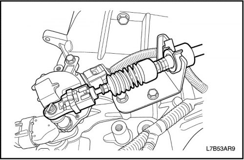
4. Disconnect the shift mechanism drive cable from the transmission. See "Shift mechanism drive cable" in this section.
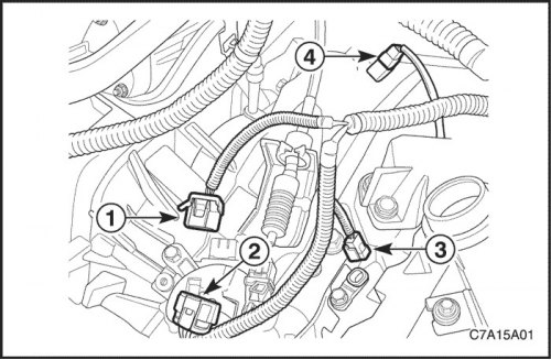
5. Disconnect the electrical connector (1) of the gear range switch.
6. Disconnect the electrical connector (2) from the transmission wiring with the final drive assembly.
7. Disconnect the electrical connector (3) of the primary shaft speed sensor and the electrical connector of the secondary shaft speed sensor (4).
8. Separate the interfering wiring harness near the gearbox with the final drive assembly.
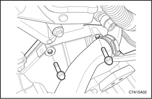
9. Remove the two upper bolts securing the gearbox with the final drive assembly to the engine.
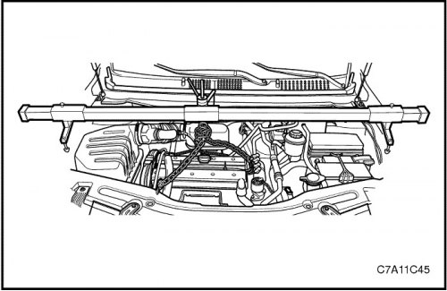
10. Install DW110-060.
11. Raise the vehicle and place it on the supports provided for this purpose.
12. Remove the engine crankcase guard. See "Section 9N, Frame and Underbody".
13. Remove the left dust cover.
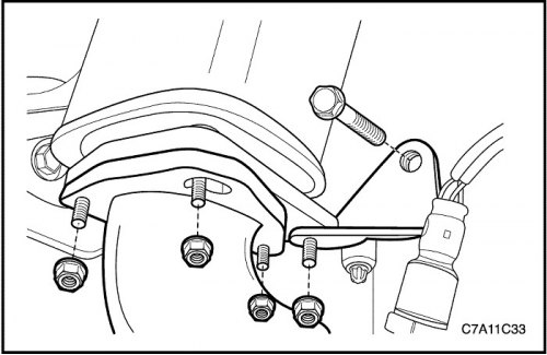
14. Remove the exhaust pipe. See Section 1G1, Engine Exhaust System - 2.0 Diesel; Section 1G2, Engine Exhaust System - FAM II 2.4D; Section 1G3, Engine Exhaust System - HFV6 3.2L.
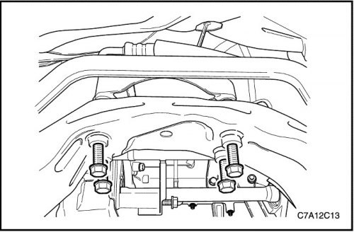
15. Carefully remove the frame from the vehicle. See Section 2C, "Front Suspension".
16. Disconnect the front axle. See Section 3A, Front Drive Axle.
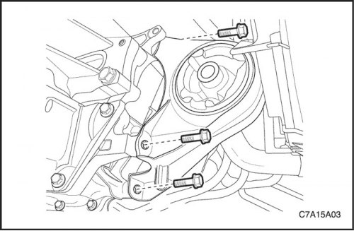
17. Loosen the front damper bushing suspension mounting bolts and remove the front damper bushing.
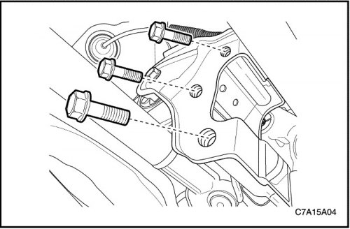
18. Unscrew the bolts securing the rear gearbox suspension bracket.
19. Remove the rear damper bushing and the rear transmission mount bracket with the final drive assembly.
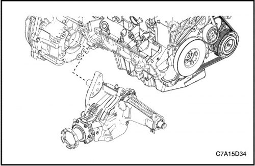
20. For AWD, remove the transfer case from the transaxle assembly. See Section 5D, Transfer Case.
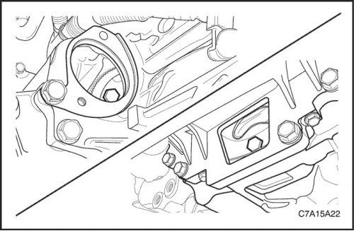
21. Remove the starter. See Section 1E1, Engine Electrical System - 2.0 Diesel; Section 1E2, Engine Electrical System - FAM II 2.4D; Section 1E3, Engine Electrical System - HFV6 3.2L.
22. Remove the six flywheel-to-torque converter mounting bolts. For the 2.0S Diesel, remove the plastic cover, then remove the six flywheel-to-torque converter mounting bolts.
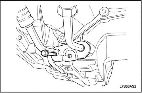
23. Remove the oil cooler line from the transaxle assembly. See "Oil Radiator Pipe Assembly" in this section.
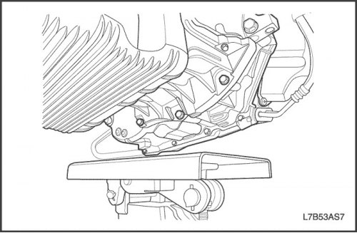
24. Support the gearbox with the final drive assembly on a jack.
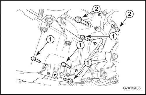
25. Loosen the bolts (1) securing the oil pan flange to the gearbox with the final drive assembly.
26. Remove the lower right engine mounting bolts to the gearbox with the final drive assembly near the front damper bushing (2).
Note: For bolt removal on HFV6 3.2L or 2.0S Diesel, See Section 1B, Engine Mechanical System - 2.0 Diesel; Section 1C2, Engine Mechanical System - HFV6 3.2L.
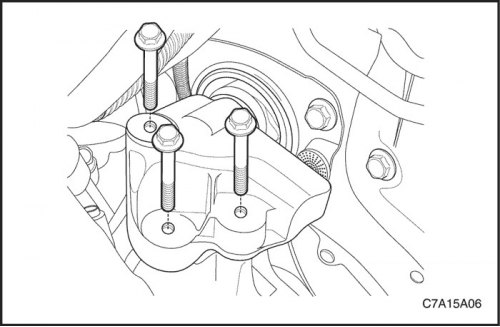
27. Remove the bolts securing the left gearbox suspension bracket with the final drive assembly. See "Left gearbox mounting bracket" in this section.
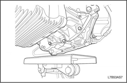
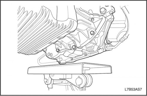
28. Carefully remove the gearbox with the final drive assembly from the vehicle.
Installation procedure
1. Install the gearbox with the final drive assembly into the vehicle and support the gearbox with the final drive assembly on a jack.
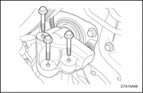
2. Install the left transmission mount bracket bolts. See "Left gearbox mounting bracket" in this section.
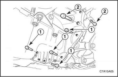
3. Install the right lower bolts (2) securing the engine to the gearbox assembly near the front damper bushing.
Tighten
Tighten the right lower bolts (2) securing the engine to the gearbox with the final drive assembly to a torque of 75 N·m (55 ft·lbs).
4. Install the bolts (1) securing the oil pan flange to the gearbox with the final drive assembly.
Tighten
Tighten the bolts (1) securing the oil pan flange to the gearbox with the final drive assembly to a torque of 50 N·m (37 ft·lbs).
Note: For installation and bolt tightening torque on HFV6 3.2L or 2.0S Diesel, See Section 1B, Engine Mechanical System - 2.0 Diesel; Section 1C2, Engine Mechanical System - HFV6 3.2L.
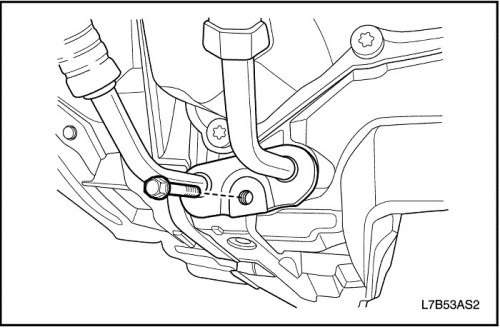
5. Install the oil cooler line to the transaxle assembly. See "Oil Radiator Pipe Assembly" in this section.
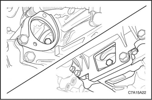
6. Install the flywheel to torque converter mounting bolts. For the 2.0S Diesel, tighten the bolts, then install the plastic cover.
Tighten
Tighten the flywheel to torque converter mounting bolts to 45 Nm (33 ft·lbs).
7. Install the starter. See Section 1E1, Engine Electrical System - 2.0 Diesel; Section 1E2, Engine Electrical System - FAM II 2.4D; Section 1E3, Engine Electrical System - HFV6 3.2L.
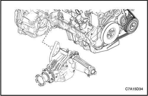
8. For AWD, install the transfer case into the transaxle assembly. See Section 5D, Transfer Case.
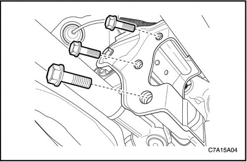
9. Install the rear damper bushing and the rear transmission mount bracket with the final drive assembly.
10. Screw in the bolts securing the rear gearbox suspension bracket.
Tighten
Tighten the rear transmission mount bracket mounting bolts to 90 N·m (66 ft·lbs).
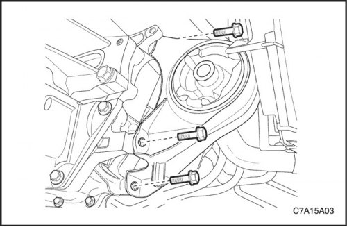
11. Install the front damper bushing and the front damper bushing suspension mounting bolts.
Tighten
Tighten the front damper bushing suspension mounting bolts to 50 Nm (37 ft·lbs).
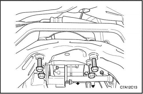
12. Connect the front axle. See Section 3A, Front Drive Axle.
13. Carefully install the frame on the vehicle. See Section 2C, "Front Suspension".
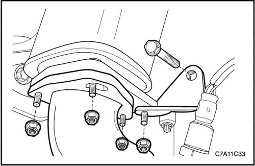
14. Install the exhaust pipe. See Section 1G1, Engine Exhaust System - 2.0 Diesel; Section 1G2, Engine Exhaust System - FAM II 2.4D; Section 1G3, Engine Exhaust System - HFV6 3.2L.
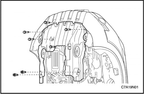
15. Install the left dust cover.
16. Install the engine crankcase guard. See "Section 9N, Frame and Underbody".
17. Lower the car.
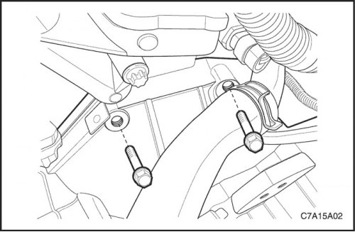
18. Install the upper transmission-to-engine mounting bolts.
Tighten
For FAM II 2.4D or 2.0S Diesel, tighten the upper gearbox assembly to engine mounting bolts to 75 Nm (55 ft·lbs).
For HFV6 3.2L, tighten the upper transmission assembly to engine mounting bolts to 50 Nm (37 ft·lbs).
19. Remove DW110-060 from the engine.
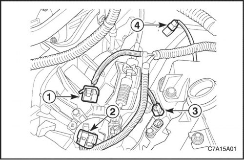
20. Connect the electrical connector (1) of the gear shift switch.
21. Connect the electrical connector (2) of the transmission wiring with the final drive assembly.
22. Connect the electrical connector (3) of the primary shaft speed sensor and the electrical connector of the secondary shaft speed sensor (4).
23. Return the interfering wiring harness back to its place near the transmission and final drive assembly.
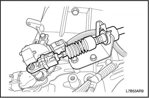
24. Install the shift control cable into the transaxle assembly. See "Shift mechanism drive cable" in this section.
25. Adjust the shift control cable. See "Adjusting the shift control cable" in this section.
26. Install the power steering fluid reservoir retaining bolts and return the reservoir to its position.
27. Install the battery and battery tray. See Section 1E1, Engine Electrical System - 2.0 Diesel; Section 1E2, Engine Electrical System - FAM II 2.4D; Section 1E3, Engine Electrical System - HFV6 3.2L.
28. Add fluid to the gearbox with the final drive assembly.
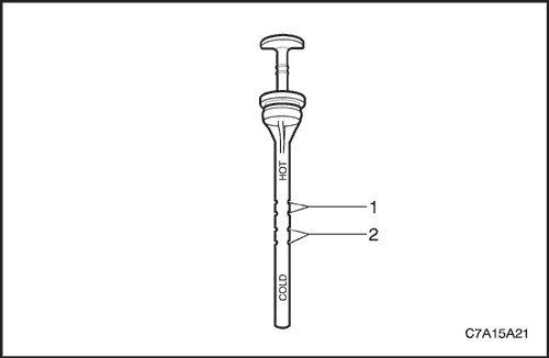
29. Check fluid level. See "Transaxle Fluid Check Procedure" in this section.
(The original text can be found on the website ChevyMan)