Contents: Removal procedure ↧ Assembly procedure ↧
Removal procedure
1. Lifting and supporting the car.
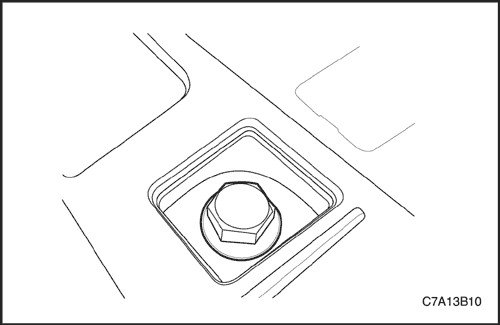
2. Remove the rear drive shaft spindle nut.
3. Remove the bolts securing the trailing arm bracket to the underbody. See Part 2D. Rear suspension.
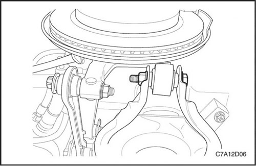
4. Remove the nut and bolt securing the toe-in lever to the steering knuckle.
5. Remove the nut and bolt securing the lower suspension arm to the steering knuckle.
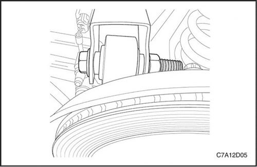
6. Loosen the nut and bolt securing the steering knuckle to the upper control arm. Do not remove the nut and bolt.
Important: Support the drive shaft while it is disconnected from the hub and wheel bearing assembly to prevent damage to the drive shaft seals.
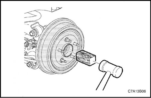
7. Place a wooden block against the drive shaft spindle and tap with a hammer to free the spindle from the hub and wheel bearing assembly.
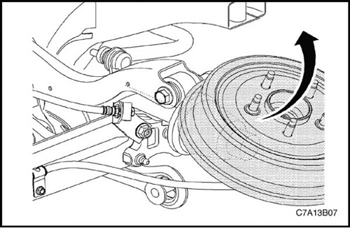
8. Turn the suspension knuckle upward and secure it with strong wire or similar means.
9. Remove the wheel drive shaft from the rear drive module (RDM).
Assembly procedure
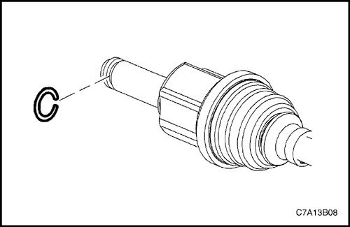
1. Install a new drive shaft snap ring onto the inner triple joint.
2. Install the wheel drive shaft onto the rear drive module (RDM) output shaft. Ensure that the triple joint is fully seated on the output shaft by firmly grasping the triple joint and attempting to pull it off the output shaft.
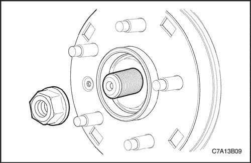
3. Rotate the suspension knuckle downward while simultaneously guiding the constant velocity (CV) joint spindle into the wheel hub and bearing assembly and into the suspension knuckle.
4. Install the new drive shaft spindle nut by hand.
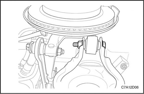
5. Install the bolt and nut securing the lower suspension arm to the steering knuckle.
Tighten
Tighten the bolt and nut securing the lower suspension arm to the steering knuckle to a torque of 160 N·m (118 ft·lbs).
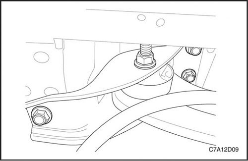
6. Install the bolts securing the trailing arm bracket to the underbody.
Tighten
Tighten the bolts securing the trailing arm bracket to the underbody to 110 Nm (81 lb-ft).
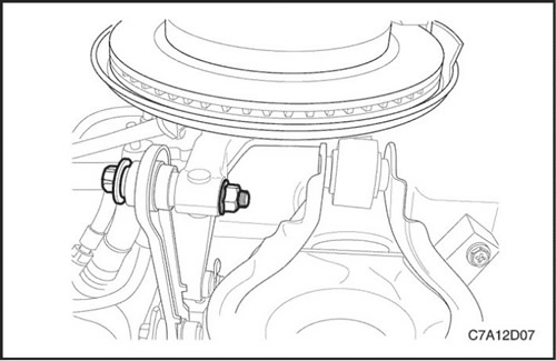
7. Install the nut and bolt securing the toe-in lever to the steering knuckle.
Tighten
Tighten the nut and bolt securing the toe-in lever to the steering knuckle to a torque of 160 N·m (118 ft·lbs).
Tighten the nut and bolt securing the steering knuckle to the upper suspension arm to a torque of 160 N·m (118 ft·lbs).
8. Check the rear wheel alignment. See section 2B, "Adjusting Wheel Alignment".