


Contents: Wheel alignment angles ↧ Difference between values for left… ↧ Tightening torques for threaded… ↧ Tire diagnostics ↧ Uneven and premature wear ↧ Tread wear indicators ↧ Rocking radial tires ↧ Lateral slip of a radial tire ↧ Table for diagnostics of lateral… ↧ Vibration diagnostics ↧ Preliminary checks ↧ Tire balancing ↧ Beating ↧ Table for diagnostics of wheel runout ↧ Preliminary inspection ↧ Adjusting the longitudinal tilt… ↧ Adjusting the front wheel camber ↧ Front wheel alignment adjustment ↧ Adjusting the rear wheel camber ↧ Rear wheel alignment adjustment ↧ Adjusting the alignment angles of… ↧ Convergence ↧ Angle of longitudinal inclination of… ↧ Collapse ↧ Tilt of the pivot axis ↧ Adjacent angle ↧ Roll shoulder ↧ Backward shift, delay ↧ Angle of rotation ↧
Wheel alignment angles
|
suspension
|
Collapse
|
Angle of longitudinal inclination of the axis of rotation
|
Convergence
|
steering
Steering wheel angle
|
Support
Corner
|
|
Front
|
-0.55°±0.75°
|
2.18°±0.73°
|
0.1°±0.08°
|
0.0°±2.5°
|
-
|
|
Rear
|
-0.35°±0.5°
|
-
|
0.09°±0.1°
|
-
|
0.0°±0.15°
|
Note: The above specifications refer to the vehicle's wheel alignment angles when turned.
Difference between values for left and right wheels
|
PROGRAM
|
Front
|
Rear
|
|
Collapse
|
1.05° max.
|
0.85° max.
|
|
Angle of longitudinal inclination of the axis of rotation
|
2.91° max.
|
-
|
|
Convergence
|
0.18° max.
|
0.19° max.
|
Tightening torques for threaded connections
|
PROGRAM
|
Nm
|
Pound foot
|
|
Bolt securing rear upper control arm to frame
|
110 Nm
|
81 lb-ft
|
|
Nut and bolt securing the strut to the steering knuckle
|
180 Nm
|
133 ft·lbs
|
|
Tie rod lock nut
|
60 Nm
|
44 ft·lbs
|
|
Bolt securing the toe-in lever to the frame
|
110 Nm
|
81 lb-ft
|
Tire diagnostics
Uneven and premature wear
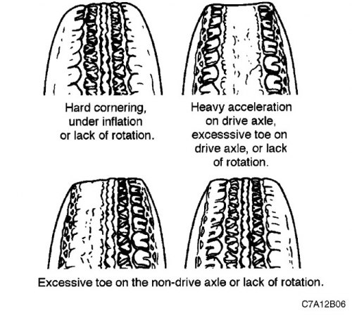
There are many causes of uneven and premature tire wear. These include, but are not limited to, incorrect tire pressure, failure to rotate wheels regularly, poor driving habits, and incorrect wheel alignment. If wheel alignment is due to tire wear, always aim to achieve a toe angle as close to zero as possible within the limits permitted by the specifications. See the section in this section "Adjusting rear wheel alignment".
Rotate the wheels if:
- The wear of the front and rear tires is not the same.
- The wear of the left and right front tires is not equal.
- The wear of the left and right rear tires is not equal.
Check the wheel alignment if:
- The wear of the left and right front tires is not equal.
- The tread of one of the front tires is worn unevenly.
- The front tire treads have sharp edges on the flange or block side.
Tread wear indicators
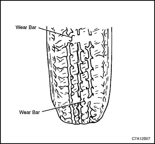
The tires installed by the vehicle manufacturer are equipped with their own tread wear indicators to help determine when the tires need to be replaced. These indicators become visible as stripes when the tread groove depth is significantly reduced. Replacement is recommended when the indicators are visible in three or more grooves in six locations.
Rocking radial tires
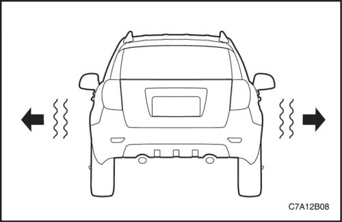
Rocking is a movement from the side to the side of the front or rear of the car. It is caused by the curvature of the steel breaker located inside the tire, or excessive lateral runout of the tire or wheel. It is most noticeable at low speeds, from 8 to 48 km / h (from 5 to 30 miles/hour), but can also manifest itself as a high-frequency vibration of the vehicle when driving at speeds from 80 to 113 km/h (from 50 to 70 miles/hour).
To determine where the faulty tire is, you need to make a test drive. If the faulty tire is installed at the rear, the rear of the car will swing. From the driver's seat, this feels like someone is pushing the car sideways. If the faulty tire is at the front, the swing can be noticed visually. It looks like the front surface of the car body is moving back and forth, and the driver's seat is the center of rotation of the car.
The cause of the rocking can be determined by successively replacing the wheels and tires with known good ones.
1. To determine whether the faulty tire is at the front or the rear, a test drive must be made.
2. Replace the faulty tires and wheels from the same model vehicle where the fault occurs. If it is not clear where the faulty tire may be, replace the rear tires.
3. Perform a test drive. If improvement is achieved, then install the old tires to identify the faulty one. If no improvement is achieved, then replace all four tires with good ones.
4. To identify the faulty tire, install the old tires one by one.
Lateral slip of a radial tire
Lateral pull is the deviation of a vehicle from straight-line motion on a level road without any force applied to the steering wheel. Typical causes of lateral pull are:
- Incorrect wheel alignment.
- Uneven brake adjustment.
- Tire construction.
Tire design features can cause the vehicle to pull sideways. Radial tire breakers that are not centered can cause lateral force when the vehicle is moving in a straight line on the road. If the tire diameter on one side is slightly larger than on the other, the tire will tend to turn to one side. Unequal tire diameters will cause lateral force, which can cause the vehicle to pull sideways.
We recommend that you use a table to diagnose lateral pull, which will help you determine whether the problem is related to the wheel alignment or the tires. When performing diagnostics, in some cases it is necessary to rotate the wheels in a sequence different from the normal one. If a tire with medium or high mileage is moved to the other side of the car, you should expect high-frequency vibration. Rear tires do not cause lateral pull.
Table for diagnostics of lateral slip of radial tires
| Step | Operation | Values | Yes | No |
| 1 |
Does the car pull sideways?
|
-
|
Go to Step 2
|
The system is working properly
|
| 2 |
Does the car pull sideways?
|
-
|
Go to Step 3
|
The system is working properly
|
| 3 |
Check the front wheel alignment angles.
Do the installation angles meet the required technical specifications?
|
-
|
Go to Step 4
|
Adjust the installation angles
|
| 4 |
Compare the camber and caster angle values with the required specifications.
Are they within the required limits?
|
- |
Go to Step 7
|
Go to Step 5
|
| 5 |
Check the car frame.
Is the frame bent?
|
-
|
Go to Step 6
|
Go to Step 1
|
| 6 |
Straighten the frame.
Is the renovation finished?
|
-
|
Go to Step 3
|
-
|
| 7 |
Does the car still pull sideways?
|
-
|
Go to Step 9
|
Go to Step 8
|
| 8 |
Swap the left front tire and wheel assembly with the left rear tire and wheel assembly and replace the left front tire.
Is the renovation finished?
|
-
|
The system is working properly
|
Go to Step 1
|
| 9 |
Does the car still pull sideways?
|
-
|
Go to Step 1
|
Go to Step 10
|
| 10 |
Swap the right front tire and wheel assembly with the right rear tire and wheel assembly and replace the right front tire.
Is the renovation finished?
|
-
|
The system is working properly
|
Go to Step 1
|
Vibration diagnostics
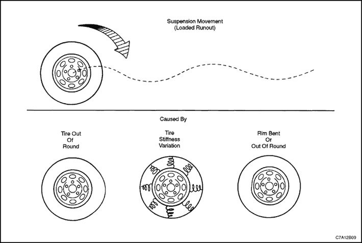
In most cases, the cause of vibration at high speeds is wheel imbalance. After dynamic balancing, vibration may persist for the following reasons:
- The tire is deformed.
- The wheel rim is deformed.
- There are variations in tire rigidity.
Measuring tire and wheel runout while freely rotating will only reveal part of the problem. All three causes, known as loaded radial runout, should be checked by replacing the faulty tire and wheel assemblies with known good ones.
The cause of vibrations occurring at low speeds not exceeding 64 km/h (40 miles/hour), usually there is a heartbeat. Cause of vibrations that occur at high speeds exceeding 64 km / h (40 miles/hour) there may be an imbalance or runout.
Preliminary checks
Before starting work, always make a test drive first and perform a thorough inspection to check for the following:
- Obvious wobble between the tire and the wheel.
- Obvious wobble of the drive axle.
- Under-inflated tires.
- Incorrect body height relative to wheels.
- Deformation or damage to wheels.
- Dirt build-up on a tire or wheel.
- Uneven or excessive tire wear.
- Incorrect position of the tire bead on the wheel rim.
- Tyre defects such as tread deformation or separation, as well as bulges caused by impact damage. Light dents on the sidewall of the tyre are not defects and do not affect the ride quality.
Tire balancing
Balancing is the simplest of all possible operations and if vibrations occur at high speed, then balancing should be performed first. First, to eliminate the imbalance of the tire with the wheel assembly, perform dynamic balancing in two planes, dismantling the tire with the wheel from the car.
Final balancing performed on the vehicle eliminates imbalances associated with the brake drum or disc, or with the wheel cap. If balancing fails to eliminate vibration at high speeds, or if vibration occurs at low speeds, then runout is likely the cause.
Beating
Runout may be related to the tire, the wheel, or the way the wheel is mounted on the vehicle. To determine if wheel runout is possible, refer to the procedures below and also use the wheel runout diagnostic chart in this section.
1. If runout is suspected, measure the lateral and radial runout of the tire and wheel assembly while freely rotating on the vehicle. See Part 2E. Tires and wheels. The values of these quantities must be less than 0.8 mm (0.03 inches). If any of the obtained values are greater, then proceed to Step 2.
2. Mount the tire and wheel on the dynamic balancing stand and measure the free-spinning lateral and radial runout again. Record the free-spinning lateral and radial runout values and the locations of the points that gave the highest values. See Part 2E. Tires and wheels. If these values exceed 1.0 mm (0.04 inches) on the tire tread, then proceed to Step 4.
3. Measure the wheel runout. See Part 2E. Tires and wheels. If the wheel is outside the acceptable technical specifications, replace it.
4. Deflate the tire and match and mount the tire on the wheel so as to bring the tire point with the large radial runout as close as possible to the wheel point with the small radial runout. Inflate the tire and mount the wheel with the tire on the dynamic balancing stand. Measure and record the free-running radial and lateral runout values and their locations. In many cases, tire and wheel balancing by matching and mounting ensures that the tire and wheel assembly runout during free rotation is within the permissible range of values not exceeding 1.0 mm (0.04 inches).
5. If the runout of the tire and wheel assembly removed from the vehicle during free rotation does not exceed 1.0 mm (0.04 inches), and after installation on the vehicle exceeds 1.0 mm (0.04 inches), then the vibration is likely caused by the installation of the wheel on the hub. Tighten any two wheel nuts and measure the runout again. See Part 2E. Tires and wheels. To determine which nuts give the best results, you may need to perform this operation several times in different places.
6. If the runout of the tire and wheel assembly cannot be reduced to less than 1.0 mm (0.04 inches), then remove the assembly.
- Measure the hub stud runout using a dial indicator with a magnetic base.
- Reset the indicator reading on one of the studs.
- Carefully move the indicator probe away from the stud. Turn the flange so that the next stud is opposite the indicator probe.
- Record the runout values for all studs. When returning to the first stud checked, the indicator should read zero.
- If the runout exceeds 0.04 mm (0.002 inches), then it is necessary to replace the hub stud or the hub and bearing assembly.
Balancing must be re-performed after each change in the position of the tire relative to the wheel or after replacing the wheel or tire.
Table for diagnostics of wheel runout
| Step | Operation | Values | Yes | No |
| 1 |
To verify that vibration occurs, perform a test drive.
Are the customer's complaints confirmed?
|
-
|
Go to Step 2
|
The system is working properly
|
| 2 |
Is the vibration still there?
|
-
|
Go to Step 3
|
The system is working properly
|
| 3 |
Determine the speed at which vibration occurs.
Is there vibration at speeds over 64 km/h? (40 miles/hour)?
|
-
|
Go to Step 4
|
Go to Step 6
|
| 4 |
Perform dynamic wheel balancing by removing the wheel from the vehicle.
Is the vibration still there?
|
-
|
Go to Step 5
|
The system is working properly
|
| 5 |
Perform final balancing on the vehicle.
Is the vibration still there?
|
-
|
Go to Step 6
|
The system is working properly
|
| 6 |
Check the lateral and radial runout of the suspended wheel on the vehicle.
Is the beat equal to the required value?
|
0.8 mm (0.03 inches)
|
Go to Step 4
|
Go to Step 7
|
| 7 |
Perform a lateral and radial runout check on the wheel removed from the vehicle.
Is the beat equal to the required value?
|
1.0 mm (0.04 inches)
|
Go to Step 8
|
Go to Step 12
|
| 8 |
Is the beat equal to the required value?
|
0.04 mm (0.002 inches)
|
Go to Step 9
|
Go to Step 14
|
| 9 |
Perform dynamic wheel balancing by removing the wheel from the vehicle.
Is the vibration still there?
|
-
|
Go to Step 10
|
The system is working properly
|
| 10 |
Perform final balancing on the vehicle.
Is the vibration still there?
|
-
|
Go to Step 11
|
The system is working properly
|
| 11 |
Have the problems been resolved?
|
-
|
Go to Step 1
|
-
|
| 12 |
Is the beat equal to the required value?
|
0.8 mm (0.03 inches)
|
Go to Step 9
|
Go to Step 13
|
| 13 |
Is the beat equal to the required value?
|
0.8 mm (0.03 inches)
|
Go to step 15
|
Step 16
|
| 14 |
Measure the hub flange runout.
Is the beat equal to the required value?
|
0.04 mm (0.002 inches)
|
Go to Step 9
|
Go to step 17
|
| 15 |
Replace the tire.
Is the renovation finished?
|
-
|
Go to Step 1
|
-
|
| 16 |
Replace the wheel.
Is the renovation finished?
|
-
|
Go to Step 1
|
-
|
| 17 |
Replace the hub.
Is the renovation finished?
|
-
|
Go to Step 1
|
-
|
Preliminary inspection
|
Checks
|
Operation, action
|
|
Check for abnormal tire pressure and tread wear.
|
Inflate tires to proper pressure. Replace tires if necessary.
|
|
Check the wheel bearings for play.
|
Replace the hub and bearing assembly.
|
|
Check the ball joints and tie rod ends for play.
|
Tighten the ball joints and tie rod ends.
|
|
Check wheel and tire runout.
|
Measure and adjust tire runout.
|
|
Check the height of the body relative to the wheels.
|
Adjust the height of the vehicle relative to the wheels. Perform the following adjustments before adjusting the toe.
|
|
Check the rack and pinion steering mechanism for play.
|
Tighten the rack and pinion assembly fasteners.
|
|
Check the proper functioning of the telescopic struts.
|
Replace the telescopic strut assembly.
|
|
Check the levers for play.
|
Tighten the control arm mounting bolts. Replace the control arm bushings if necessary.
|
Adjusting the longitudinal tilt angle of the front wheel steering axis
The caster angle of the front steering axis is not adjustable. If the caster angle of the front steering axis does not meet the required specifications, check the correct installation of the suspension support and the presence of damage to the front suspension. Replace damaged suspension parts if necessary.
Adjusting the front wheel camber
1. Raise and support the vehicle.
2. Remove the tires and wheels as an assembly.
3. Remove the nuts and bolts securing the strut to the steering knuckle. Discard the nuts and bolts.
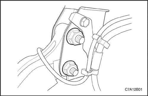
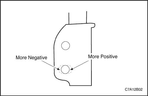
4. If the rack has not been modified previously, follow this procedure:
- Disconnect the strut from the steering knuckle.
- If negative camber increases, remove material from the outside of the lower strut hole.
- If the negative camber is reduced, remove material from the inside of the lower strut hole.
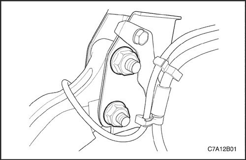
5. Install new bolts and put on new nuts securing the strut to the steering knuckle.
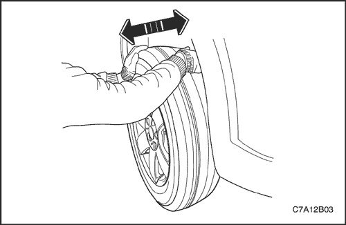
6. Adjust the camber to the desired specifications, moving the top of the tire in or out as necessary.
7. Tighten the rack mounting nuts and bolts.
Tighten
Tighten the nuts and bolts to a torque of 180 Nm (133 ft·lbs).
8. Install the tires and wheels assemblies.
Front wheel alignment adjustment
1. Move the steering wheel to this position and lock it so that the car wheels are pointing straight ahead.
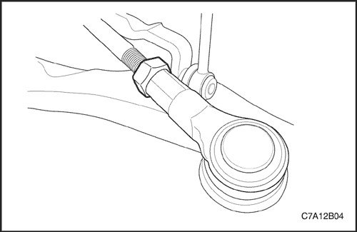
2. Loosen both inner tie rod locknuts.
Important: The inner tie rod must rotate freely without touching the boot sealing surface. Do not allow the boot to rotate.
3. Loosen the inner tie rod seal against the boot surface.
4. Use a wrench and flats on the tie rod to increase or decrease the toe angle specifications.
5. Tighten the inner tie rod locknuts.
Tighten
Tighten the locknuts to a torque of 60 Nm (44 ft·lbs).
6. Check the toe angle to ensure proper adjustment and adjust if necessary.
Adjusting the rear wheel camber
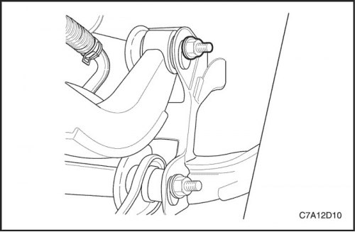
1. Loosen the upper control arm to the frame just enough to allow movement.
Important: There are grooves on the car frame; by turning the cam nut, you can move the camber to the designated position.
2. Rotate the upper control arm mount in the direction required to obtain the correct camber measurement.
3. Firmly seat the upper control arm mount to the frame without tightening it.
4. Recheck the rear wheel camber specifications and adjust if necessary.
5. While holding the nut, tighten the upper control arm to frame mounting bolt.
Tighten
Tighten the bolt to a torque of 110 Nm (81 lb-ft).
6. Repeat this procedure for the other rear wheel.
Rear wheel alignment adjustment
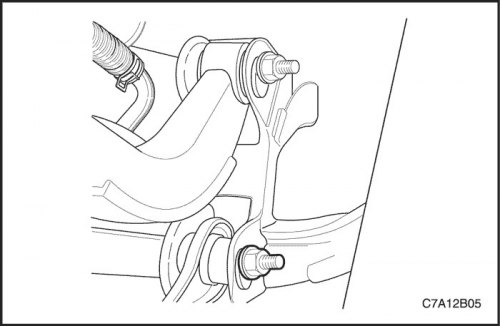
1. Loosen the toe link to the frame just enough to allow movement.
2. Turn the toe lever cam nut in the direction required to adjust the toe angle.
3. Firmly seat the toe-in lever mount onto the frame without tightening it.
4. Recheck the rear wheel alignment specifications and adjust if necessary.
5. While holding the nut, tighten the bolt securing the lever to the frame.
Tighten
Tighten the bolt to a torque of 110 Nm (81 lb-ft).
6. Repeat this procedure for the other rear wheel.
Adjusting the alignment angles of all four wheels
The first responsibility of the designers is to create safe steering and suspension systems. Each component must be strong enough to withstand extreme loads. Both the steering and the rear and front suspensions must function in such a way as to ensure that the geometric characteristics are maintained in the presence of the body weight.
To ensure that engine control requires minimal effort and is as comfortable as possible, the steering and suspension must ensure that the front wheels return automatically and that the tire rolling force and rolling friction force are maintained at negligible values.
A complete wheel alignment check should include rear wheel toe and camber measurements.
Adjusting the alignment angles of all four wheels ensures that the wheels move in exactly the same direction.
A vehicle with adjusted geometric parameters has the best fuel consumption and tire life, and its handling and performance characteristics reach their maximum.
Convergence
With positive toe-in, the wheels are turned inward, and with negative toe-in, outward relative to the geometric centerline or line of action of the traction. Toe-in ensures parallel movement of the wheels.
Toe-in serves to compensate for small deviations in the wheel mounting system that occur when the vehicle is moving forward. The toe-in angle that must be obtained during adjustment is the toe-in that becomes equal to zero degrees when the vehicle is moving.
Incorrect positive or negative toe-in will cause tire wear and increased fuel consumption. As the vehicle is driven, steering and suspension components wear, additional toe-in adjustments will be required to compensate for this wear.
Always adjust toe last.
Angle of longitudinal inclination of the axis of rotation
Caster is the angle at which the top of the steering axis is tilted forward or backward from the vertical when viewed from the side of the vehicle. Caster is positive toward the rear and negative toward the front. Caster affects the ability of the steering to maintain the vehicle's heading, but does not affect tire wear. Caster is affected by spring slack and vehicle overload. A wheel with a smaller caster angle will tend to be pulled toward the center of the vehicle. In this case, the vehicle will tend to move or lean toward the wheel with the smaller positive caster angle. Caster is measured in degrees and is not adjustable.
Collapse
Camber is the deviation of the top of the tire from the vertical when viewed from the front of the vehicle. If the tires are tilted outward, the camber is positive. If the tires are tilted inward, the camber is negative. The camber angle is measured in degrees relative to the vertical. Camber affects both the vehicle's ability to maintain a desired course and tire wear.
If the positive camber of a car wheel is too great, the outer shoulder of the tire will wear out. If the negative camber of a car wheel is too great, the inner shoulder of the tire will wear out.
Tilt of the pivot axis
Steering axis inclination is the deviation of the top of the steering knuckle from the vertical. Steering axis inclination is measured between the true vertical and a line through the center of the strut and the lower ball joint when viewed from the front of the vehicle.
The steering axis inclination helps maintain the straight-line motion of the vehicle and return the wheel in the direction of straight-line motion. The steering axis inclination for vehicles with front drive axles should be negative.
Adjacent angle
The included angle is the angle measured from the camber angle to a line passing through the center of the strut and the lower ball joint when looking at the vehicle from the front.
The included angle is calculated in degrees. Most rigs that are designed to adjust the installation angles do not directly measure the included angle. To determine the included angle, subtract the negative camber from the tilt of the steering axis or add the positive camber to the tilt of the steering axis.
Roll shoulder
The rolling shoulder is the distance along the road surface between the true vertical and a line passing through the center of the strut and the lower ball joint. The rolling shoulder is built into the vehicle design. The rolling shoulder is not adjustable.
Backward shift, delay
Rearward setback is the distance that a front hub and bearing assembly can be offset from another front hub and bearing assembly. Rearward setback is primarily caused by road obstructions or collisions.
Angle of rotation
Steering angle is the angle at which each front wheel turns relative to the vertical axis when the vehicle is turning.