


Loosen the front wheel mounting nuts, remove the front wheel hub caps and loosen the hub adjusting nuts.
Set the gearbox and transfer case levers to neutral position.
Raise the car and remove the front wheels.
Remove the crankcase guard and engine splash guards.
Drain the oil from the front axle gearbox housing.
Loosen the nuts of the bolts securing the flanges of the cardan shaft and the front axle gearbox. Turn the front cardan shaft to disconnect it from the gearbox.
Bend back the edges of the locking plates and unscrew the nuts securing the muffler inlet pipe to the exhaust manifold. Then unscrew the bolts securing the clamp of the muffler inlet pipe to the gearbox and the bolts securing the pipe to the additional muffler and move the muffler inlet pipe toward the engine.
Disconnect the right shock absorber rod from the mounting bracket, unscrew the nut of the shock absorber mounting bolt to the lower arm, remove the bolt and remove the shock absorber.
Loosen the right hub nut and remove the conical bushing.
Place a support under the right lower arm and, having lowered the car, compress the front suspension spring until the upper arm rebound buffer begins to unload. Then install the brackets on the spring and fix the spring in the compressed position.
Loosen the three nuts securing the lower ball joint to the lower arm and remove the bolts.
Raise the vehicle, disconnect the ball joint from the control arm, move the hub to the side and remove the outer drive joint tip from the hub.
Loosen and remove the inner joint bearing cover mounting bolt 22 (see figure 3-76) right (and then the left one) drive to the front suspension cross member.
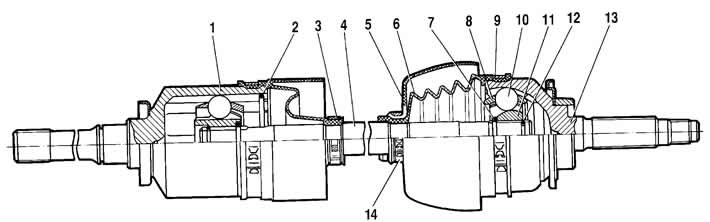
Figure 3-76. Front wheel drive:
1 - inner hinge housing;
2 - retainer;
3 - cover fastening clamp;
4 - wheel drive shaft;
5 - protective cover of the case;
6 - protective cover;
7 - thrust ring of the cage;
8 - separator;
9 - cover fastening clamp;
10 - ball;
11 - outer hinge cage;
12 - retaining ring;
13 - outer hinge housing;
14 - casing fastening clamp.
Unscrew the four nuts securing the lower cover 2 of the front axle reducer to the stabilizer bar.
Unscrew the three nuts securing the bearing cover of the inner joint of the right drive to the gearbox.
Turn the wheels all the way to the right, holding the gearbox, remove the drive from the gearbox housing until the studs are released, unfold the hinge bearing cover and remove the right drive assembly.
Temporarily secure the left drive inner joint bearing cover to the front suspension crossmember with a bolt and the lower gearbox cover to the stabilizer bar with nuts.
Remove the left shock absorber, cone bushing and remove the outer drive joint tip from the left hub, following the operations specified above for the right side.
Loosen the bolt and nuts installed temporarily and remove the front axle gearbox with the left drive assembly.
Unscrew the three nuts securing the bearing cover of the inner joint of the left drive to the front axle gearbox and disconnect the left drive from the gearbox.
Installation is carried out in the reverse order of removal. When installing the bridge, tighten the nuts and bolts to the torques specified in Appendix 1.
Pour transmission oil into the front axle housing through the oil filler hole; the oil level should reach the lower edge of the hole.
The source of the article is available on the website: «CHEVYMAN.ru»