


Assemble and adjust the front axle gearbox following the instructions given in the subsection "Rear axle", while increasing the distance "D" (see figure 3-73) should be 0.08-0.11 mm. When adjusting the gearbox, use bracket 67.8701-9508 with a measuring tip and key 67.7812-9571.
Install on housing 9 (see figure 3-75) inner hinge cover 12 of the bearing with seal 8, then press on bearing 7. Install spring washer 10 and retaining ring 11.
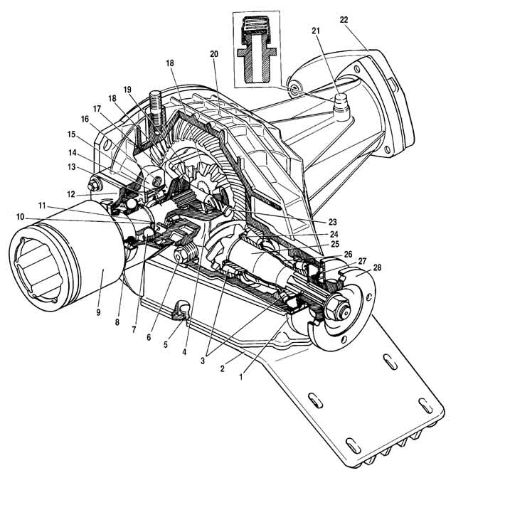
Figure 3-75. Front axle:
1 - mud deflector;
2 - lower cover of the gearbox housing;
3 - pinion bearings;
4 - differential housing;
5 - drain plug;
6 - filler and inspection hole plug;
7 - inner joint housing bearing;
8 - oil seal;
9 - inner joint housing of the wheel drive;
10 - spring washer;
11 - retaining ring;
12 - bearing cap;
13 - adjusting nut;
14 differential box bearing;
15 - bearing cap;
16 - cover mounting bolt;
17 - support washer;
18 - axle gear;
19 - satellite;
20 - gearbox housing;
21 - breather;
22 - inner joint bearing cover;
23 - satellite axis;
24 - adjusting ring;
25 - drive gear;
26 - bearing spacer sleeve;
27 - pinion seal;
28 - flange.
Note: The left seal of the inner joint (semi-axle) has a mark on the frame in the form of an annular groove for distinction.
Install the inner joint assembly into the crankcase, having first put the sealing gaskets on the studs. Tighten the nuts securing the joint bearing caps.
[The material was created based on information from the website chevyman.ru]