


The disassembly procedure is as follows:
- loosen clamps 9 and 14 (see figure 3-77), remove them from the rubber boot 6 and from the casing and slide the casing with the boot on the shaft to open access to the sleeve 11 of the joint;
- using a punch and a hammer, knock the collar 11 off the shaft;
Warning: To prevent the locking ring 12 from jamming, it is important to prevent the clip from becoming skewed by choosing the right force and direction of impact.
- slide thrust ring 7, protective cover 6 and casing 5 off shaft 4;
- move the protective cover of the inner joint on the shaft and, having removed the retainer 2, remove the shaft 4 from the housing 1, complete with the collar, separator and balls;
- using a punch and a hammer, knock the inner joint collar off shaft 4;
- after removing the thrust ring, slide the protective cover off the shaft;
- wash the internal cavities of the hinge housings and other parts.
The most complex and responsible operations are those of disassembling and assembling the outer hinge, the parts of which are shown in Figure 3-77. Good quality of disassembling and assembling operations is ensured by following the techniques below.
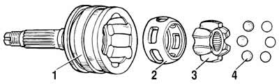
Figure 3-77. Front wheel drive outer joint components:
1 - hinge housing;
2 - separator;
3 - clip;
4 - ball.
Mark the relative positions of the collar, separator, and joint housing with paint. Secure the outer joint in a vice as shown in Figure 3-78. Tilt the collar and separator so that one ball comes out of the joint housing groove as completely as possible. Use a soft metal screwdriver to push the ball out of the separator. Then turn all the parts so that the adjacent ball takes the same position and remove it from the separator. Using the above techniques, remove the remaining balls. The sequence of removing the balls from the separator may be different - every other ball.
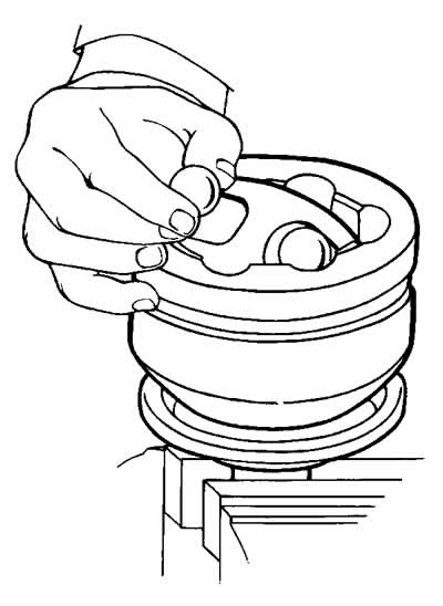
Figure 3-78. Removing the ball from the separator.
Light tapping on the separator or cage with an object made of soft material is allowed. Excessive force when turning the separator is unacceptable, as it may block the balls, which will complicate further disassembly.
Install the separator with the collar so that the elongated holes of the separator are located against the projections of the hinge housing (see figure 3-79) and remove the separator assembly with the clip.
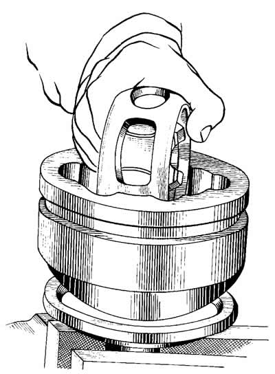
Figure 3-79. Removing the separator assembly with the collar from the hinge housing.
Remove the clip from the separator by placing one of the clip's projections in the separator's elongated opening (see figure 3-80) and then roll the clip out towards the straight edge of the hole. Wash all parts and blow them out with compressed air.
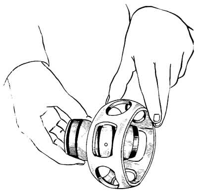
Figure 3-80. Removing the clip from the separator.
The outer joint is assembled in the reverse order of disassembly, taking into account the following:
- before assembly, lubricate all parts with SHRUS-4 grease;
- when installing the separator assembly with the collar into the hinge housing, ensure that the marks applied before disassembly match, place the collar with the annular groove (under the thrust ring) towards the shaft, and the separator - with the chamfer towards the bottom of the hinge housing;
- when installing balls into the separator, tilt the cage at an angle approximately twice as large as the separator;
- fill the joint with 60 cm³ of SHRUS-4 grease;
- before hitting the shaft 4 (see figure 3-76) to connect it to the inner race 11, it is necessary to install a new retaining ring 12 strictly in the center, and then sharply hit down on the end of the shaft; the retaining ring will compress and slide through the splined hole in the cage;
- when pressing the hinge housing oil seal ring, use a mandrel.
After assembly, the collar may block when the shaft is rocked, when the ball does not rotate. This is not a sign of poor assembly, since such blocking will not occur when the hinge rotates during operation.
Using the above techniques, completely disassemble the inner joint. In this case, the cage must be removed towards the large diameter of the separator.
Assemble the inner joint in the reverse order. In this case, it is necessary to align the marks applied before disassembly. The elongated conical part of the separator should be directed towards shaft 4. When assembling, fill the joint with SHRUS-4 grease in the amount of 150 cm.
When installing the hinge protective covers, use a mandrel.
If there are no knocks or vibrations, and the protective covers are in good condition, then disassembling the front wheel drive is not recommended.