
Contents: Identification procedure ↧ Removal procedure ↧ Clear, clean ↧ Inspection ↧ Installation procedure ↧ Valve timing drive assembly (hMC… ↧ Identification procedure ↧
Identification procedure
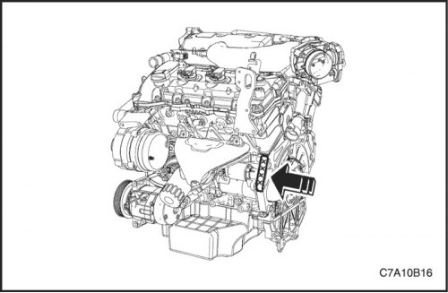
1. The engine number is stamped on the cylinder block under the exhaust manifold of engine No.6. Make sure that the engine number looks like this: "10HMA XXXXX~"
2. If the engine number "10HMC XXXXX~", go to the section "Valve timing actuator assembly (hMC engine)".
Necessary equipment
EN-46105 Camshaft Locking Tool Kit
EN-46108 Timing Chain Holding Tool Kit
EN-46111 Crankshaft turning device
Important! Setting the valve timing is required in all cases where the camshaft drive system has been affected and it is necessary to ensure that the required relationship between any chain and sprocket has not been disrupted. Even if this applies to only one sprocket, repeated crankshaft rotations will not reproduce conditions in which the correct valve timing can be maintained. To set the valve timing, if required, follow the instructions for installing the secondary timing chain components for bank 2.
Removal procedure
Cylinder bank 1
1. Remove the cylinder head cover of cylinder bank 1. See "Cylinder head cover" in this section.
2. Remove the camshaft position sensor. See Section 1F3, Engine Controls - HFV6 3.2L.
3. Remove the valve timing actuator solenoid valves See Section 1F3, Engine Controls - HFV6 3.2L.
4. Remove the crankshaft pulley. See "Crankshaft pulley" in this section.
5. Install the EN-46111 crankshaft turning tool onto the crankshaft.
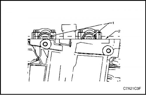
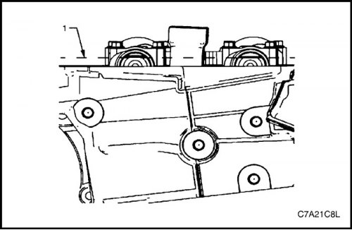
6. Turn the crankshaft so that the camshafts are in the neutral position, in which the chain is slack. The flats (1) of the camshaft will be parallel to the joint surface (2) with the cylinder head cover.
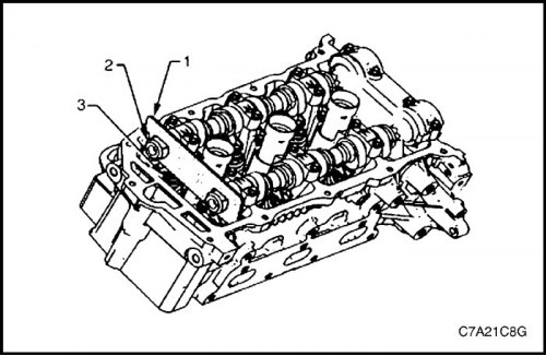
7. Install the EN-46105-1 tool (1) onto the camshafts (2) of cylinder bank 1 of the cylinder head (3).
Note:
To prevent the camshaft/engine from rotating, use a spanner (1) and place it on the hexagon (2) of the camshaft. The oil pump should only be disassembled when troubleshooting lubrication system faults. A disassembled oil pump cannot be reused and must be replaced.
At this stage, you should not remove the valve timing drive bolt.
8. Loosen the valve timing drive bolt.
Note: If the camshaft drive chain has already been removed, proceed to step 12.
Important: It is essential that the EN-46108 jaws completely encircle the camshaft drive chain, the wing nuts are tightened and the chain is tensioned.
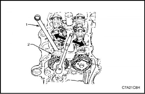
9. Install the EN-46108 tool (1 and 2) to hold (3 and 4) the camshaft timing chain.
10. Firmly tighten the EN-46108 fixture wing nuts.
Note: Mark the camshaft timing chain and variable valve timing actuators to ensure correct subsequent assembly.
11. Mark the camshaft drive chain and, where appropriate, both valve timing actuators.

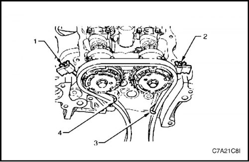
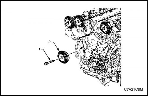
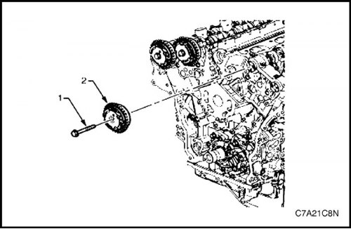
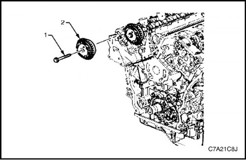
12. Remove the bolt (1) securing the drive (2) for adjusting the valve timing of the exhaust camshaft of cylinder bank 1 and remove the drive.
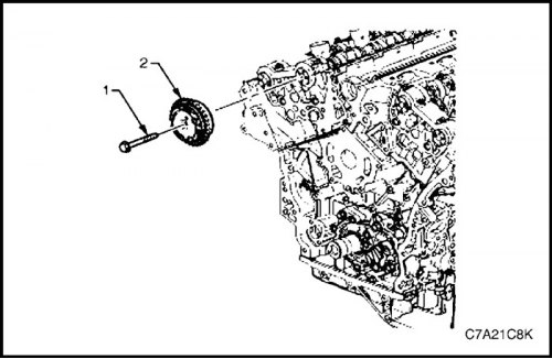
13. Remove the bolt (1) securing the drive (2) for adjusting the valve timing of the intake camshaft of cylinder bank 1 and remove the drive.
Cylinder bank 2
1. Remove the cylinder head cover of cylinder bank 2. See "Cylinder head cover" in this section.
2. Remove the camshaft position sensor. See Section 1F3, Engine Controls - HFV6 3.2L.
3. Remove the valve timing actuator solenoid valves See Section 1F3, Engine Controls - HFV6 3.2L.
4. Remove the crankshaft pulley. See "Crankshaft pulley" in this section.
5. Install the EN-46111 crankshaft turning tool onto the crankshaft.
6. Turn the crankshaft so that the camshafts are in the neutral position, in which the chain is slack. The flats (1) of the camshaft will be parallel to the joint surface (2) with the cylinder head cover.
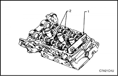
7. Install the EN-46105-1 tool (1) onto the camshafts (2) of cylinder bank 2 of the cylinder head.

Note:
To prevent the camshaft/engine from rotating, use a spanner (1) and place it on the hexagon (2) of the camshaft.
At this stage, you should not remove the valve timing drive bolt.
8. Loosen the valve timing drive bolt.
Note: If the camshaft drive chain has already been removed, proceed to step 12.

Important: It is essential that the EN-46108 jaws completely encircle the camshaft drive chain, the wing nuts are tightened and the chain is tensioned.
9. Install the EN-46108 tool (1 and 2) to hold (3 and 4) the camshaft timing chain.
10. Firmly tighten the EN-46108 fixture wing nuts.
Note: Mark the camshaft timing chain and variable valve timing actuators to ensure correct subsequent assembly.
11. Mark the camshaft drive chain and, where appropriate, both valve timing actuators.
12. Remove the bolt (1) securing the drive (2) for adjusting the valve timing of the exhaust camshaft of cylinder bank 1 and remove the drive.
13. Remove the bolt (1) securing the drive (2) for adjusting the valve timing of the intake camshaft of cylinder bank 1 and remove the drive.
Clear, clean
1. Clean the outside of each valve timing actuator with solvent.
2. Dry the valve timing components with compressed air.
Inspection
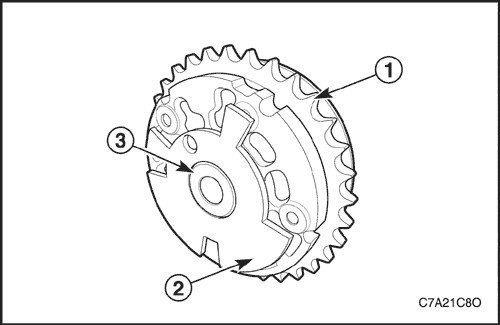
1. Inspect the front of each variable valve timing drive for the following faults:
- Sprocket damage (1),
- Damage to the interrupter/sensor gear (2),
- Damage to the inner seating/sealing surface of the hub flange (3) of the valve timing drive bolt.
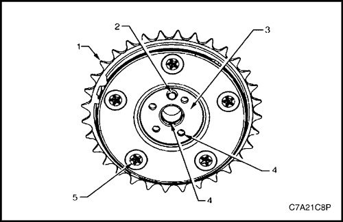
2. Inspect the rear of each variable valve timing drive for the following faults:
- Sprocket damage (1),
- Damage to the camshaft dowel pin (2),
- Damage to the inner seating/sealing surface of the hub flange (3),
- Clogged oil passages (4),
- Loose or missing housing bolts (5).
Installation procedure
1. Installation should be carried out in the reverse order of removal of parts.
2. Align the marks made on the valve timing drives and on the camshaft drive chain made before removal.
3. Install the valve timing control drives.
Tighten
Tighten the variable valve timing actuator mounting bolts to 58 N·m (43 lb-ft).
4. Remove the timing chain retaining devices.
Valve timing drive assembly (hMC engine)
Identification procedure
1. The engine number is stamped on the cylinder block under the exhaust manifold of engine No.6. Make sure that the engine number looks like this: "10HMC XXXXX~".
2. If the engine number "10HMA XXXXX~", go to the section "Valve timing actuator assembly (hMA engine)".
Necessary equipment
EN-46105 Camshaft Locking Tool Kit
EN-48313 Timing chain retainer
EN-46111 Crankshaft turning device
The article is based on data from the website: «ChevyMan»