
Note: If the information contained in this section differs from the information on the release control label (located on the right front shock absorber in the engine compartment of the car), the information on the plate should be considered correct.
1. The engine must be warmed up to normal operating temperature and the air conditioner must be turned off.
2. Set the vehicle's parking brake and block the wheels to prevent the vehicle from moving. The gearbox must be set to the park position.
3. If the lamp is on "SERVICE ENGINE SOON" ("perform urgent engine maintenance"), do not start checking the ignition advance angle (for more information on this issue, see chapter 6).
4. Before checking the ignition timing, the Electronic Spark Control (EST) system should be inspected. Locate the single wire with a black stripe attached to the engine wiring harness at the front right shock absorber mount (next to the release control information sign) and disconnect the connector (see illustration). Do not disconnect the four-wire harness connector at the distributor.
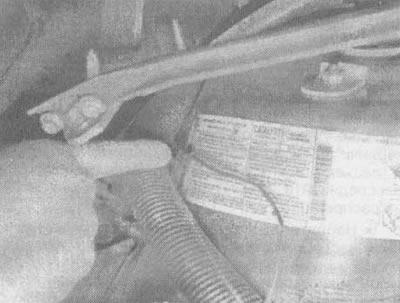
34.4 Disconnect the EST wire before checking the ignition timing setting
5. Locate the timing marks on the front of the engine (they should be visible from above after opening the hood) (see illustration). The crankshaft pulley or vibration damper has a mark and a small metal plate with teeth and numbers attached to the timing cover. Clean the plate with solvent to make the numbers more visible.
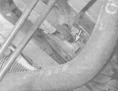
34.5. Ignition timing angle setting marks (indicated by an arrow) located on the front of the engine
6. Using chalk or white paint, mark the indentation or groove on the pulley/anti-vibration device.
7. Select the mark on the timing plate that matches the ignition timing data on the exhaust control information plate (most often it says 0 degrees or TDC).
8. Connect the strobe light following the manufacturer's instructions. In general, the supply wires are attached to the battery terminals, and the sensor wire is attached to the spark plug wire of the 1st cylinder. To find this cylinder, see section "Technical data" in chapter 2, part 2.1.
9. Make sure the synchronization lamp wires are routed away from the drive belts and fan, then start the engine.
10. After the engine idle speed has stabilized, aim the strobe light at the timing marks, but beware of moving engine parts!
11. The mark on the pulley/damper will appear to be stationary. If it is aligned with the specified point on the synchronizing plate, then the ignition timing angle is set correctly.
12. If the marks are not aligned, adjustment is required. Loosen the distributor mounting bolt and very slowly turn the distributor until the marks align. Since the bolt is difficult to access, a special key may be required.
13. Tighten the bolt and check the ignition timing again.
14. Turn off the engine and remove the strobe light and adapter (if it was used).
15. Reconnect the EST harness connector and clear any ECM fault codes that were set during the ignition timing adjustment procedure (see chapter 6).