
ChevyMan.ru
Mazda Mitsubishi Toyota Land Rover Honda Kia Nissan
English Русский
Български
Беларускі
Український
Српски
Hrvatski
Română
Polski
Slovenský
Magyar
|
Articles | Sitemap | Contacts |


Home   Aveo   Captiva   Cruze   Lacetti   Lanos   Niva   Tahoe   Others  
Orlando 1 (2010-2018) Trailblazer 1 (2001-2008, petrol) Lumina 1 (1989-1994)
  • Home
  • Chevrolet
  • Orlando 1
  • Power unit
  • Fuel and control system
  • Variable valve timing valve

Variable valve timing valve (Chevrolet Orlando 1)

            0

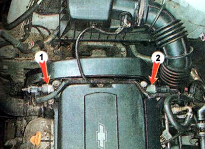
The car's engine is equipped with an automatic variable valve timing system, both at the intake and exhaust. Variable Exhaust Valve (camshaft of exhaust valves) 1 installed on the front wall of the cylinder head, intake valve timing control (intake valve camshafts) 2 is installed on the rear wall.

The car's engine is equipped with an automatic variable valve timing system, both at the intake and…


The car's engine is equipped with an automatic variable valve timing system, both at the intake and…

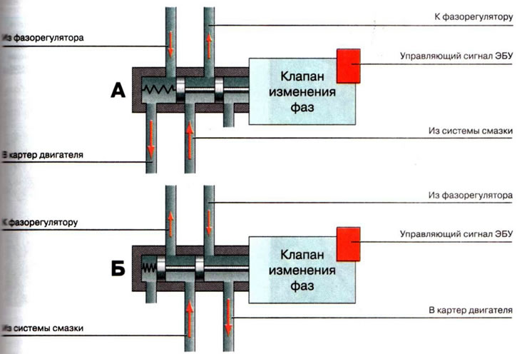
Direction of oil flow: A - valve is off; B - valve is on

The system is driven by engine oil pressure in the engine lubrication system and is controlled by the engine control unit (ECU) using electromagnetic valves.

The system's actuators are two hydraulically controlled phase regulators installed in the camshaft pulleys. Oil enters the phase regulator from the engine lubrication system through the phase change valve. It can be supplied through one of two channels, while it returns to the engine oil sump through the free channel. Depending on the direction of oil movement through the phase regulator, the angle of rotation of the shaft relative to its pulley is set and the valve timing is shifted. The flow of oil into the phase regulator is changed according to the commands of the electronic control unit. Depending on the engine operating modes, the ECU turns the valve on or off, and the valve locking mechanism connects the oil channels of the system in a certain way.


After the engine stops, the springs return the phase regulators to their original position. If the valve timing change valve or its electrical circuit is faulty, the normal operation of the system will be disrupted, fuel consumption will increase, and engine power will decrease. At idle and in transient modes, the engine may operate unstably. The engine management system malfunction indicator light may also come on. To identify the causes of the malfunction, it is necessary to diagnose the engine management system and check the phase change valve. The faulty valve must be replaced.

Replacement. The work is shown using the example of replacing the exhaust phase change valve, the intake phase change valve is replaced in a similar way.


To complete the job you will need a new valve gasket, a multimeter and two pieces of wire.

1. We prepare the car for maintenance and repair.

2. Move the locking mechanism.
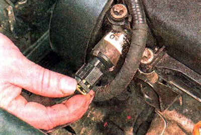
2. Move the locking mechanism.


3. Press the lock...
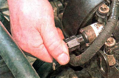
3. Press the lock...


...and disconnect the wiring harness from the valve that changes the exhaust phase.
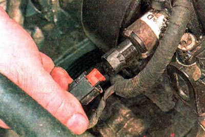


...and disconnect the wiring harness from the valve that changes the exhaust phase.


4. Inspect the connector and make sure there is no corrosion or damage. If necessary, we treat it with a special agent for cleaning electrical contacts and clean the contacts from oxides.

5. Connect the positive probe of the multimeter, switched on in voltage measurement mode, to contact 2 of the wiring harness block, connect the negative probe to the ground and turn on the ignition. The multimeter should show the battery voltage. If there is no voltage, then check the electrical circuit to fuse Ef47 in the engine compartment fuse and relay box.

Note. You can check the serviceability of the electromagnetic valve by measuring the resistance at its terminals, which should be within 7-20 Ohms. When voltage is applied from the battery to the valve terminals, it should operate with a characteristic click.
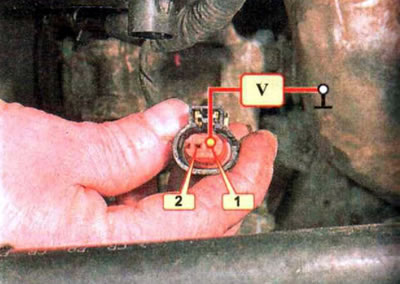

Note. You can check the serviceability of the electromagnetic valve by measuring the resistance at…


6. Using a TORX E8 socket wrench, unscrew the mounting bolt and remove the valve. The connection is sealed with a rubber ring, which must be replaced when reinstalled.
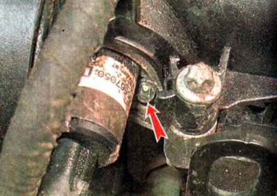


6. Using a TORX E8 socket wrench, unscrew the mounting bolt and remove the valve. The connection is…


7. Install the valve with a new sealing ring in the reverse order. Before installation, apply a thin layer of motor oil to the sealing ring. Tighten the valve mounting bolt to a torque of 7-9 Nm.

[For details, visit the website chevyman.ru]

The article was checked: Vladimir Romannikov
This article is available at russian, bulgarian, belarusian, ukrainian, serbian, croatian, romanian, polish, slovak, hungarian

Share information:

Previous articles
Orlando 1: Fuel and control system
Next articles

Catalytic converter
Throttle assembly
Engine Management System Diagnostics
Intake Air Temperature Sensor
Camshaft Position Sensor
Evaporative Canister Purge Valve
Cleaning the fuel supply system
Pre-start heater
Exhaust gas system
Engine management system


See similar articles on the topic of Chevrolet cars:
Replacing valve stem seals Chevrolet Aveo T300 (2012-2018)
Replacing the variable valve timing drive — row 2 (left side), exhaust Chevrolet Captiva 1 (2006-2018)
Replacing valve stem seals Chevrolet Cruze 1 (2008-2016)
Removal the valve and vacuum reservoir of the variable intake tract system Chevrolet Lacetti 1 (2002-2009)
Removal the exhaust gas recirculation valve Chevrolet Lanos T150 (2002-2009)
Cylinder head and valve mechanism Chevrolet Niva 1 (2002-2016)
Variable valve timing system Chevrolet Tahoe 2 and 3 (2000-2014)
Link in different formats to this page


Visitor comments

No comments yet


How much will 40 + 37 =


Orlando 1 (2010-2018) 
  • General information
  • Introduction to manual
  • User manual
  • Maintenance
  • Troubleshooting
  • Power unit
  • Engine repair
  • Fuel and control system
  • Cooling and lubrication system
  • Ignition system
  • Transmission
  • Clutch
  • Gearbox
  • Drive shafts
  • Chassis
  • Car suspension
  • Steering
  • Brake system
  • Body
  • Exterior (external elements)
  • Doors, locks and windows
  • Electrical equipment
  • Equipment and devices
  • Windscreen wipers
  • Power devices
  • Electrical diagrams


Trailblazer 1 (2001-2008) 
  • General information
  • User manual
  • Troubleshooting
  • Maintenance
  • Power unit
  • Engine in a car
  • Engine overhaul
  • Cooling and heating
  • Fuel and exhaust system
  • Engine electrical equipment
  • Engine control
  • Transmission
  • Automatic gearbox
  • Transfer case
  • Drive shafts and cardan
  • Chassis
  • Brake system
  • Car suspension
  • Steering
  • Body
  • Exterior (external elements)
  • Interior (internal elements)
  • Doors, locks and windows
  • Electrical equipment
  • Equipment and devices
  • Electrical circuits


Lumina 1 (1989-1994) 
  • General information
  • Maintenance
  • Power unit
  • Engine 3.1L V6
  • Engine 3.8L V6
  • Engine overhaul
  • Cooling system
  • Power and exhaust system
  • Fuel injection
  • Engine electrical equipment
  • Reduced exhaust gas toxicity
  • Transmission
  • Automatic gearbox
  • Drive shafts
  • Chassis
  • Brake system
  • Car suspension
  • Steering
  • Body
  • Heating and air conditioning
  • Repair of body elements
  • Doors, covers and windows
  • Interior (internal elements)
  • Electrical equipment
  • Equipment and devices
  • Electrical circuits


ChevyMan.ru © 2017-2026 · Mobile version · Feedback · Site search · Interesting to read · Sitemap: EN BG BY UA RS HR RO PL SK HU

Aveo 2003-2008 · Aveo 2006-2011 · Aveo 2012-2018 · Captiva 2006-2018 · Cruze 2008-2016 · Lacetti 2002-2009 · Lanos 2002-2009 · Niva 2002-2016 · Tahoe 1992-2000 · Tahoe 2000-2014 · Lumina 1 1989-1994 · Trailblazer 1 2001-2008 · Orlando 1 2010-2018 ·
🛡️ For your security and to improve our service, this site uses cookies. You can disable them in your browser.