


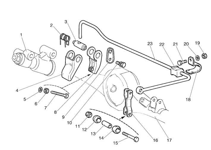
Figure 6-24. Pressure regulator drive parts:
1 - pressure regulator;
2 - lever spring;
3 - axis of the regulator drive lever;
4 - pressure regulator drive piston lever;
5 - spring washer;
6 - nut;
7 - adjusting bolt;
8 - pressure regulator drive lever;
9 - lever support plate;
10 - bolt with spring washer;
11 - nut of bolt 15;
12, 14 - plastic sleeve;
13 - spacer sleeve;
15 - traction control mounting bolt;
16 - connecting rod of pressure regulator drive lever with rear axle bracket;
17 - rear axle beam;
18 - support sleeve housing;
19 - nut;
20 - spring washer;
21 - bolt for fastening the clip to the bracket;
22 - drive lever support sleeve;
23 - pressure regulator drive lever.
Disconnect the muffler suspension parts from the body and move the pipeline with the mufflers to the side.
After unscrewing the bolts securing the regulator to the bracket and the bracket to the body, remove the regulator bracket, and then, lowering the regulator down, disconnect the pipes from it.
Remove the regulator and disconnect the drive lever from it. Plug the inlet and outlet openings of the pressure regulator and pipelines.
Install the pressure regulator in the reverse order of removal. Before installing the rod 5 (figure 6-5) check the correct adjustment of the regulator drive and, if necessary, perform it as described in the section "Adjusting the pressure regulator drive".
Bleed the brakes to remove air from the rear brake system.
The pressure regulator regulates the pressure in the hydraulic drive of the rear wheel brake mechanisms depending on the load on the rear axle of the car. It is included in both circuits of the brake system and through it the brake fluid is supplied to both rear brake mechanisms.
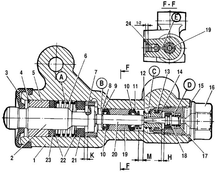
Figure 6-25. Rear brake pressure regulator in the non-working position:
1 - pressure regulator housing;
2 - piston;
3 - protective cap;
4, 8 - retaining rings;
5 - piston bushing;
6 - piston spring;
7 - body bushing;
9, 22 - support washers;
10 - Pusher sealing rings;
11 - support plate;
12 - pusher bushing spring;
13 - valve seat sealing ring;
14 - valve seat;
15 - sealing gasket;
16 - cork;
17 - valve spring;
18 - valve;
19 - Pusher bushing;
20 - pusher;
21 - piston head seal;
23 - piston rod seal;
24 - plug;
A, D - chambers connected to the master cylinder;
B, C - chambers connected to the wheel cylinders of the rear brakes;
K, M, H - gaps.
The regulator has four chambers: A and D (figure 6-25) are connected to the master cylinder, B to the left, and C to the right wheel cylinders of the rear brakes.
In the initial position of the brake pedal, piston 2 (see figure 6-25) pressed by lever 6 (see figure 6-5) through spring 5 to pusher 20 (see figure 6-25), which, under this force, is pressed against the seat 14 of the valve 18. In this case, the valve 18 is pressed away from the seat and a gap H is formed, as well as a gap K between the piston head and the seal 21. Through these gaps, chambers A and D communicate with chambers B and C.
When the brake pedal is pressed, the fluid enters the wheel cylinders of the brake mechanisms through the gaps K and H and the chambers B and C. As the fluid pressure increases, the force on the piston increases, tending to push it out of the housing. When the force from the fluid pressure exceeds the force from the elastic lever, the piston begins to move out of the housing, and after it, the pusher 20 moves under the action of springs 12 and 17 together with the bushing 19 and rings 10. In this case, the gap M increases, and the gaps H and K decrease. When the gap H is completely selected and the valve 18 isolates the chamber D from the chamber C, the pusher 20 together with the parts located on it stops moving after the piston. Now the pressure in chamber C will change depending on the pressure in chamber B. With a further increase in the force on the brake pedal, the pressure in chambers D, B and A increases, piston 2 continues to move out of the housing, and bushing 19 together with sealing rings 10 and plate 11 under increasing pressure in chamber B, moves towards plug 16. In this case, gap M begins to decrease. Due to the decrease in the volume of chamber C, the pressure in it, and therefore in the brake drive, increases and will be practically equal to the pressure in chamber B. When gap K becomes equal to zero, the pressure in chamber B, and therefore in chamber C, will increase to a lesser extent than the pressure in chamber A due to throttling of the fluid between the piston head and seal 21. The relationship between the pressure in chambers B and A is determined by the ratio of the difference in the areas of the head and the piston rod to the area of the head.
As the vehicle load increases, the elastic lever 6 (see figure 6-5) is loaded more and the force from lever 2 on the piston increases, that is, the moment of contact between the piston head and seal 21 (see figure 6-25) is achieved with higher pressure in the main brake cylinder. Thus, the efficiency of the rear brakes increases with increasing load.
In case of failure of the brake circuit "left front - right rear brakes", sealing rings 10, bushing 19 under the pressure of the liquid in chamber B will shift towards plug 16 until plate 11 stops in seat 14. The pressure in the rear brake will be regulated by the part of the regulator, which includes piston 2 with seal 21 and bushing 7. The operation of this part of the regulator, in case of failure of the named circuit, is similar to the operation with a serviceable system. The nature of the change in pressure at the regulator outlet is the same as with a serviceable system.
When the brake circuit "right front - left rear brakes" fails, the pusher 20 with the bushing 19 and sealing rings 10 is displaced towards the piston by the brake fluid pressure, pushing it out of the housing. The gap M increases, and the gap H decreases. When the valve 18 touches the seat 14, the pressure increase in chamber C stops, i.e. the regulator in this case works as a pressure limiter. However, the achieved pressure value is sufficient for reliable operation of the rear brake.
In the housing 1 there is a hole closed by a plug 24. The leakage of liquid from under the plug when it is squeezed out indicates a leak in the rings 10.