
ChevyMan.ru
Mazda Mitsubishi Toyota Land Rover Honda Kia Nissan
English Русский
Български
Беларускі
Український
Српски
Hrvatski
Română
Polski
Slovenský
Magyar
|
Articles | Sitemap | Contacts |


Home   Aveo   Captiva   Cruze   Lacetti   Lanos   Niva   Tahoe   Others  
Niva 1 (2002-2016)
  • Home
  • Niva
  • 1 (2002-2016)
  • Chassis
  • Brake system
  • Disassembly and assembly of rear brake wheel cylinders

Disassembly and assembly of rear brake wheel cylinders (Chevrolet Niva 1)

            0

Disassemble and assemble wheel cylinders as follows.

Remove protective caps 2 (figure 6-20), then press out pistons 4 from cylinder body 3 together with the parts of the automatic clearance adjustment device between the brake shoes and the drum.

Figure 6-20. Wheel cylinder:

Figure 6-20. Wheel cylinder:
1 - brake shoe stop;
2 - protective cap;
3 - cylinder body;
4 - piston;
5 - seal;
6 - support cup;
7 - spring;
8 - crackers;
9 - thrust ring;
10 - stop screw;
11 - nipple;
A - slot on the thrust ring.


Install the piston assembly with the automatic device on a special fixture so that the projections of the fixture cover the head of the stop screw 3 (figure 6-21). Using a screwdriver, turn piston 9 and unscrew stop screw 3 from the piston. Remove seal 8 with support cup 7 and crackers 5 from the screw. Disconnect stop ring 4 and stop screw 3.
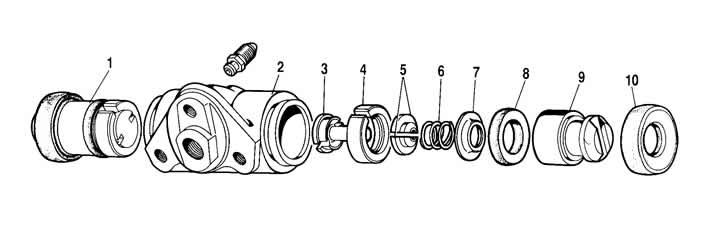
Figure 6-21. Wheel cylinder parts:

Figure 6-21. Wheel cylinder parts:
1 - piston assembly;
2 - cylinder body;
3 - stop screw;
4 - thrust ring;
5 - crackers;
6 - spring;
7 - support cup;
8 - seal;
9 - piston;
10 - protective cap.


Assemble the automatic device and the wheel cylinder itself in the reverse order, taking into account the following:


  • tighten the piston stop screws with a torque of 4...7 Nm (0.4...0.7 kgf·m);
  • slot A (see figure 6-18) on the thrust rings should be directed vertically upwards; deviation from the vertical is allowed no more than 30°. This location of the slot ensures more complete removal of air from the brake mechanism drive during its bleeding;
  • to pre-compress the thrust rings, press the pistons into the cylinder body using a special device shaped like a cylinder with a conical inner hole;
  • the force required to press the piston into the cylinder must be at least 350 N (35 kgf); if the force is less than 350 N (35 kgf), replace the thrust ring;
  • when pressing the piston into the cylinder, it is necessary to maintain dimensions of 4.5 - 4.8 mm and 67 mm (maximum) (see figure 6-18) for free fit of brake drum;
  • before installing the parts into the cylinder body, lubricate them generously with brake fluid.
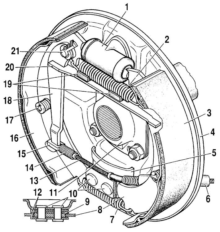
Figure 6-18. Rear wheel brake mechanism:

Figure 6-18. Rear wheel brake mechanism:
1 - wheel cylinder;
2 - upper brake shoe tension spring;
3 - pad pad;
4 - brake shield;
5 - inner plate;
6 - rear cable sheath;
7 - lower brake shoe tension spring;
8 - front brake shoe;
9 - Brake pad support plate;
10 - rivets;
11 - oil deflector;
12 - brake shoe guide plates;
13 - rear parking brake cable;
14 - rear cable spring;
15 - rear cable tip;
16 - rear brake shoe;
17 - support stand of the shoe;
18 - manual brake pad drive lever;
19 - rubber cushions;
20 - brake shoe spacer bar;
21 - finger of the manual brake shoe drive lever.


After assembly, check the movement of each piston in the cylinder body. They should move easily within 1.25-1.65 mm. Lastly, install the protective caps 2.

The source of the article is available on the website: chevyman

The article was checked: Vladimir Romannikov
This article is available at russian, bulgarian, belarusian, ukrainian, serbian, croatian, romanian, polish, slovak, hungarian

Share information:

Previous articles
Niva 1: Brake system
Next articles

Assembly and installation of the rear brake
Removal and disassembling the rear brake
Rear brake device
Replacing the front brake pads
Checking the runout of the front brake disc
Checking the rear brake components
Checking the rear brake wheel cylinders on the stand
Rear brake pressure regulator
Parking brake


See similar articles on the topic of Chevrolet cars:
Removal and installation the rear wheel brake drum Chevrolet Aveo T300 (2012-2018)
Rear wheel brake hose Chevrolet Captiva 1 (2006-2018)
Replacing the rear wheel brake caliper assembly Chevrolet Cruze 1 (2008-2016)
Replacement of protective covers and sealing rings of pistons of brake cylinders of front and rear wheels Chevrolet Lacetti 1 (2002-2009)
Replacing the rear wheel brake cylinder Chevrolet Lanos T150 (2002-2009)
Rear Brake Wheel Cylinder — Removal, Disassembly and Installation Chevrolet Tahoe 1 (1992-2000)
Removal, repair and installation of the rear wheel brake cylinder Chevrolet Lumina 1 (1989-1994)
Link in different formats to this page


Visitor comments

No comments yet


How much will 25 + 24 =


Niva 1 (2002-2016) 
  • General information
  • Vehicle device
  • User manual
  • Maintenance
  • Power unit
  • Engine repair
  • Cooling system
  • Lubrication system
  • Power and exhaust system
  • Transmission
  • Clutch
  • Car gearbox
  • Transfer case
  • Cardan gear
  • Rear axle
  • Front axle
  • Chassis
  • Suspension and shock absorbers
  • Steering
  • Brake system
  • Body
  • Exterior (external elements)
  • Interior (internal elements)
  • Ventilation and heating
  • Electrical equipment
  • Power devices
  • Lighting and appliances


ChevyMan.ru © 2017-2026 · Mobile version · Feedback · Site search · Interesting to read · Sitemap: EN BG BY UA RS HR RO PL SK HU

Aveo 2003-2008 · Aveo 2006-2011 · Aveo 2012-2018 · Captiva 2006-2018 · Cruze 2008-2016 · Lacetti 2002-2009 · Lanos 2002-2009 · Niva 2002-2016 · Tahoe 1992-2000 · Tahoe 2000-2014 · Lumina 1 1989-1994 · Trailblazer 1 2001-2008 · Orlando 1 2010-2018 ·
🛡️ For your security and to improve our service, this site uses cookies. You can disable them in your browser.