
ChevyMan.ru
Mazda Mitsubishi Toyota Land Rover Honda Kia Nissan
English Русский
Български
Беларускі
Український
Српски
Hrvatski
Română
Polski
Slovenský
Magyar
|
Articles | Sitemap | Contacts |


Home   Aveo   Captiva   Cruze   Lacetti   Lanos   Niva   Tahoe   Others  
Lanos T150 (2002-2009)
  • Home
  • Lanos
  • T150 (2002-2009)
  • General information
  • Troubleshooting
  • Checking injectors and their control circuits

Checking injectors and their control circuits (Chevrolet Lanos T150)

            0

We check the performance of the injectors when we detect malfunctions in the engine operation.

We begin checking the injector control circuits by checking the integrity of fuse F14 (15A) of the mounting block located in the passenger compartment.

Failure of fuse F14 can also be caused by a malfunction of the generator circuits, vehicle speed sensor, canister purge valve, or exhaust gas recirculation valve.

We replace the faulty fuse with a new one, having first checked whether there is a short circuit to ground at the front terminal of the fuse socket in the mounting block.

To check the power supply circuits of the injectors (power "+") with the ignition off, disconnect the pads (4 pcs) of the wiring harness from the injectors.

With the ignition on…
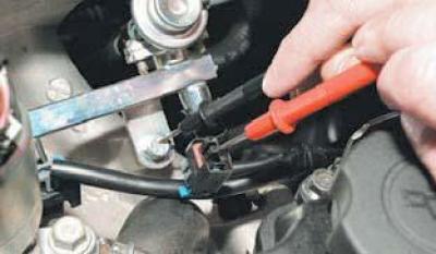
…we measure the voltage between terminal «1» and the engine «ground» for each injector.


…we measure the voltage between terminal "1" and the engine "ground" for each injector.

The device should record a voltage equal to the voltage of the vehicle's on-board network.

We also check the serviceability of the injector control circuits (open or short to ground) between terminal "2" of the wiring harness connector of each injector and the corresponding terminal of the ECU wiring harness connector for each cylinder: 1st cylinder - terminal "M25"; 2nd cylinder - terminal "M22"; 3rd cylinder - terminal "M24"; 4th cylinder - terminal "M11".


To check the injector winding with the ignition off, disconnect the engine control system wiring harness connector from it (see Removal the fuel rail and injectors).

Having connected the tester probes to the injector terminals…
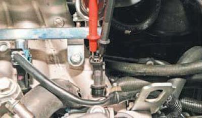
…we check the winding resistance.


…we check the winding resistance.

A serviceable injector should have a winding resistance of 11.6–12.4 Ohms.

To check the functionality of the injector, the quality of the spray and the tightness of the sprayer, remove the fuel rail (see Removal the fuel rail and injectors).

We connect the tip of the pressure line tube to the ramp fitting, and the tip of the drain line tube to the fuel pressure regulator branch pipe.

We install the fuel pump fuse in place.

We check each injector one by one, placing a container underneath it to collect the fuel.

After turning on the ignition, we directly supply 12 V voltage from the battery to the injector terminals using two wires.

The operation of checking the quality of fuel atomization by the injector is fire hazardous.


Avoid sparking when applying voltage to the injector.
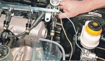
The fuel jets should emerge from the injector nozzle with a characteristic spray cone.


The fuel jets should emerge from the injector nozzle with a characteristic spray cone.


After disconnecting the wires from the injector, we check whether fuel is leaking through the holes of the injector nozzle.

Fuel leakage should not exceed one drop per minute.

We check other injectors in the same way.

If the electrical resistance of the injector winding does not correspond to the norm, the amount of injected fuel and the spray pattern differ greatly from the indicators of other injectors, or the injector is leaky, it must be replaced.

The article was checked: Vladimir Romannikov
This article is available at russian, bulgarian, belarusian, ukrainian, serbian, croatian, romanian, polish, slovak, hungarian

Share information:

Previous articles
Lanos T150: Troubleshooting
Next articles

Checking the Manifold Absolute Pressure Sensor
Checking the speed sensor
Checking the intake manifold air temperature sensor
Checking the coolant temperature sensor and its circuits
Checking the phase sensor and its circuits
Checking the pressure in the engine fuel system
Checking the fuel pump activation circuit
Transmission, chassis, steering and braking system
Electrical equipment fault table


See similar articles on the topic of Chevrolet cars:
Ventilation system with manual control unit Chevrolet Aveo T300 (2012-2018)
Remote control unit Chevrolet Captiva 1 (2006-2018)
Gearbox control Chevrolet Cruze 1 (2008-2016)
Checking the condition of wheels and tires Chevrolet Lacetti 1 (2002-2009)
Checking the sensors of control devices Chevrolet Niva 1 (2002-2016)
Transfer case with manual control Chevrolet Tahoe 1 (1992-2000)
Checking and repairing electrical circuits Chevrolet Orlando 1 (2010-2018)
Link in different formats to this page


Visitor comments

No comments yet


How much will 26 + 37 =


Lanos T150 (2002-2009) 
  • General information
  • User manual
  • Maintenance
  • Troubleshooting
  • Power unit
  • Engine repair
  • Control system
  • Supply system
  • Cooling system
  • Exhaust system
  • Transmission
  • Clutch
  • Car gearbox
  • Front wheel drives
  • Chassis
  • Front suspension
  • Rear suspension
  • Steering
  • Brake system
  • Body
  • Repair of body elements
  • Heating and air conditioning
  • Electrical equipment
  • Engine electrics
  • Lighting and lamps
  • Equipment and devices
  • Electrical circuits


ChevyMan.ru © 2017-2026 · Mobile version · Feedback · Site search · Interesting to read · Sitemap: EN BG BY UA RS HR RO PL SK HU

Aveo 2003-2008 · Aveo 2006-2011 · Aveo 2012-2018 · Captiva 2006-2018 · Cruze 2008-2016 · Lacetti 2002-2009 · Lanos 2002-2009 · Niva 2002-2016 · Tahoe 1992-2000 · Tahoe 2000-2014 · Lumina 1 1989-1994 · Trailblazer 1 2001-2008 · Orlando 1 2010-2018 ·
🛡️ For your security and to improve our service, this site uses cookies. You can disable them in your browser.