ChevyMan.ru
Mazda Mitsubishi Toyota Land Rover Honda Kia Nissan
English Русский
Български
Беларускі
Український
Српски
Hrvatski
Română
Polski
Slovenský
Magyar
|
Articles | Sitemap | Contacts |


Home   Aveo   Captiva   Cruze   Lacetti   Lanos   Niva   Tahoe   Others  
Orlando 1 (2010-2018) Trailblazer 1 (2001-2008, petrol) Lumina 1 (1989-1994)
  • Home
  • Chevrolet
  • Lumina 1
  • Power unit
  • Fuel injection
  • Throttle Body — Removal and Installation (3.1L)

Throttle Body — Removal and Installation (3.1L) (Chevrolet Lumina 1)

            0

62. Disconnect all electrical connectors from the IAC valve, TPS sensor and injectors. Disconnect the wiring harness from the throttle body.

63. Disconnect the throttle body linkage, return springs, transmission control cable and, if equipped, the cruise control.

64. Label and then disconnect all vacuum hoses.

65. Using the holding auxiliary key, unscrew the nuts of the inlet and outlet pipes of the fuel line (see illustration). Remove and replace the fuel line O-rings.

12.65. When loosening the nuts securing the fuel supply and drain lines, do not forget to use an…

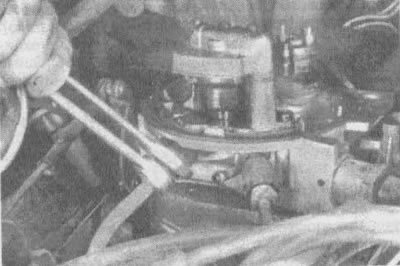
12.65. When loosening the nuts securing the fuel supply and drain lines, do not forget to use an auxiliary holding key to prevent damage (twisting) highways


66. Remove the nuts securing the TBI block (see illustration), and remove the block from the intake manifold. Remove and replace the TBI manifold gasket.

12.66. To disconnect the throttle body of the 220 model from the intake manifold, unscrew the three…

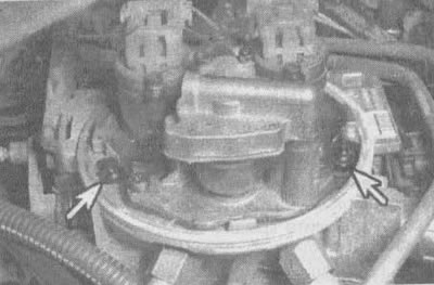
12.66. To disconnect the throttle body of the 220 model from the intake manifold, unscrew the three nuts (indicated by arrows) (the third nut is not visible here)


67. Place the TBI block on the locking stand (Kent-Moore J-9789-118, BT-3553 or their equivalent) Note: If you do not have a stand and want to place the TBI block directly on the workbench surface (work bench), be extremely careful when servicing it - the throttle can be easily damaged.

68. Remove the screws securing the fuel flow meter housing to the throttle body and remove the meter housing from the throttle body.

69. Remove the gasket between the throttle body and the fuel flow meter body and replace it.

70. Remove the TPS unit.

71. Turn the throttle body upside down on a flat surface for greater stability and remove the IAC valve.

72. Clean the throttle body in cold cleaner. Clean metal parts thoroughly and dry with compressed air. Make sure all fuel and air passages and passages are free of dirt and burrs.

Caution: Do not immerse TPS, IAC valves, pressure regulator diaphragm, injectors or other parts containing rubber in solvent or cleaning bath. If it is necessary to clean the throttle body, the time it remains in the cleaning solution should be kept to a minimum. Some models have dust boots on the throttle body that may lose their effectiveness after being in solvent.


73. Inspect the mating surfaces for damage that may compromise the sealing of the gaskets. Inspect the throttle lever and valve for dirt or damage.

74. Turn the throttle body upside down on a flat surface for stability and install the IAC valve and TPS.

75. Install a new gasket between the throttle body and the fuel flow meter housing and install the meter to the throttle body. Apply sealant to the screws that secure the fuel flow meter housing to the throttle body and tighten them securely.


76. Install the TBI unit and tighten the nuts to the torque specified in the specifications of this chapter. Use a new gasket between the TBI block and the manifold.

77. Install new O-rings on the fuel line nuts. Tighten the fuel inlet and outlet nuts by hand to avoid stripping the threads. Using a wrench to prevent the lines from twisting, tighten the nuts securely after they are properly seated in the TBI block.

78. Connect the vacuum hoses, throttle body linkage, return springs, transmission control cable, and, if equipped, cruise control. Attach the grommet with the wire harness to the throttle body.

79. Connect all electrical connectors, ensuring they are fully seated and snapped into place.

80. Check the accelerator pedal travel.

81. Connect the cable to the battery and, after stopping the engine and turning on the ignition, check for leaks on the fuel supply and drain line nuts.

82. Adjust the minimum idle speed and check the TPS output signal (see paragraphs 84-93).

83. Install the air filter, adapters and gaskets.

(The article is based on data from the website CHEVYMAN.RU)

The article was checked: Vladimir Romannikov
This article is available at russian, bulgarian, belarusian, ukrainian, serbian, croatian, romanian, polish, slovak, hungarian

Share information:

Previous articles
Lumina 1: Fuel injection
Next articles

Fuel flow meter — removal and installation (3.1 l)
Idle Air Control Valve (IAC, 3.1L)
Throttle Position Sensor (TPS, 3.1L)
Injector housing — removal and installation (3.1 l)
Fuel Pressure Regulator and Fuel Gauge Cap (3.1L)
Adjusting the minimum idle speed (3.1 l)
Checking the unregulated signal of the TPS sensor (3.1 L)
Throttle Body — Removal and Installation (3.8L)
Idle Air Control Valve (IAC, 3.8L)
Throttle Position Sensor (TPS, 3.8L)


See similar articles on the topic of Chevrolet cars:
Throttle body Chevrolet Aveo T250 (2006-2011)
Electronic throttle body Chevrolet Captiva 1 (2006-2018)
Removal and installation the throttle assembly Chevrolet Cruze 1 (2008-2016)
Removal the throttle assembly Chevrolet Lacetti 1 (2002-2009)
Checking the throttle position sensor and its circuits Chevrolet Lanos T150 (2002-2009)
Car body care Chevrolet Niva 1 (2002-2016)
Checking the tightening torque of the throttle body mounting bolts Chevrolet Tahoe 1 (1992-2000)
Link in different formats to this page


Visitor comments

No comments yet


How much will 25 + 32 =


Orlando 1 (2010-2018) 
  • General information
  • Introduction to manual
  • User manual
  • Maintenance
  • Troubleshooting
  • Power unit
  • Engine repair
  • Fuel and control system
  • Cooling and lubrication system
  • Ignition system
  • Transmission
  • Clutch
  • Gearbox
  • Drive shafts
  • Chassis
  • Car suspension
  • Steering
  • Brake system
  • Body
  • Exterior (external elements)
  • Doors, locks and windows
  • Electrical equipment
  • Equipment and devices
  • Windscreen wipers
  • Power devices
  • Electrical diagrams


Trailblazer 1 (2001-2008) 
  • General information
  • User manual
  • Troubleshooting
  • Maintenance
  • Power unit
  • Engine in a car
  • Engine overhaul
  • Cooling and heating
  • Fuel and exhaust system
  • Engine electrical equipment
  • Engine control
  • Transmission
  • Automatic gearbox
  • Transfer case
  • Drive shafts and cardan
  • Chassis
  • Brake system
  • Car suspension
  • Steering
  • Body
  • Exterior (external elements)
  • Interior (internal elements)
  • Doors, locks and windows
  • Electrical equipment
  • Equipment and devices
  • Electrical circuits


Lumina 1 (1989-1994) 
  • General information
  • Maintenance
  • Power unit
  • Engine 3.1L V6
  • Engine 3.8L V6
  • Engine overhaul
  • Cooling system
  • Power and exhaust system
  • Fuel injection
  • Engine electrical equipment
  • Reduced exhaust gas toxicity
  • Transmission
  • Automatic gearbox
  • Drive shafts
  • Chassis
  • Brake system
  • Car suspension
  • Steering
  • Body
  • Heating and air conditioning
  • Repair of body elements
  • Doors, covers and windows
  • Interior (internal elements)
  • Electrical equipment
  • Equipment and devices
  • Electrical circuits


ChevyMan.ru © 2017-2026 · Mobile version · Feedback · Site search · Interesting to read · Sitemap: EN BG BY UA RS HR RO PL SK HU

Aveo 2003-2008 · Aveo 2006-2011 · Aveo 2012-2018 · Captiva 2006-2018 · Cruze 2008-2016 · Lacetti 2002-2009 · Lanos 2002-2009 · Niva 2002-2016 · Tahoe 1992-2000 · Tahoe 2000-2014 · Lumina 1 1989-1994 · Trailblazer 1 2001-2008 · Orlando 1 2010-2018 ·
🛡️ For your security and to improve our service, this site uses cookies. You can disable them in your browser.