


Note: Due to the relative ease of replacing parts, the throttle body does not need to be disconnected from the intake manifold or disassembled. However, for clarity, the work performed is shown using the example of a TBI unit removed from a vehicle.
1. Relieve the fuel pressure in the system (see section 2).
2. Disconnect the cable from the negative terminal of the battery.
3. Remove the air filter, adapter and gaskets.
Note: The fuel pressure regulator is located in the fuel flow meter cover. Each time the meter cover or the regulator itself is replaced, the entire unit must be replaced. The regulator cannot be removed from the cover.
4. Disconnect the electrical connectors from the injectors.
5. Remove the long and short fuel gauge cover screws (see illustration) and remove the lid.
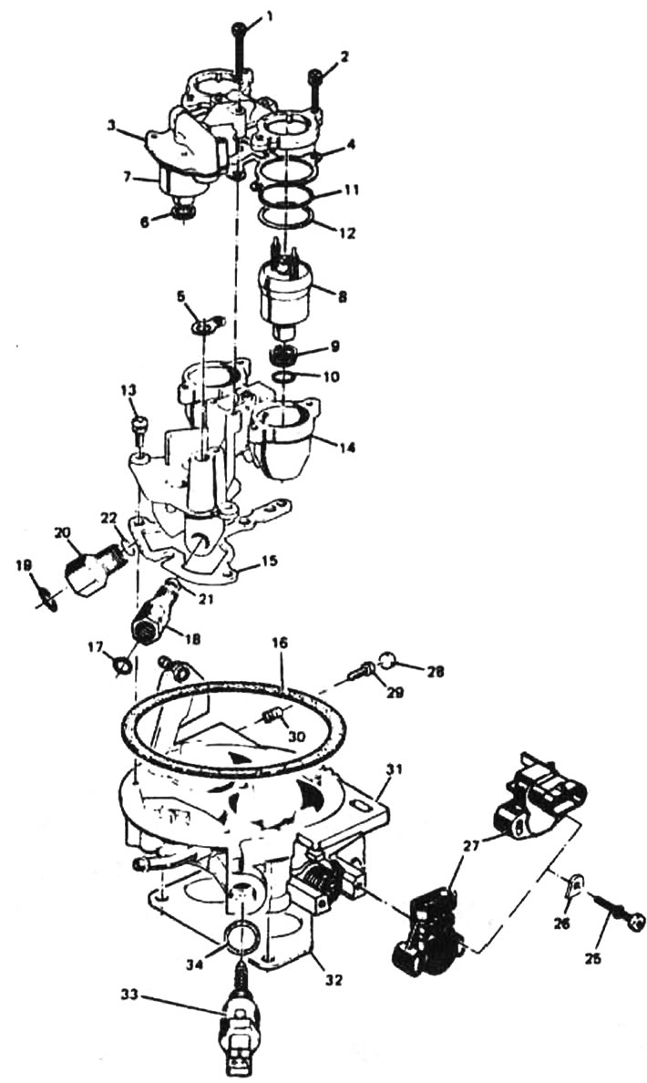
12.5. TBI Block Model 220 Parts: 1 - long screw for securing the fuel flow meter cover; 2 - short screw for securing the fuel flow meter cover; 3 - fuel flow meter cover; 4 - Fuel flow meter cover gasket; 5 - Fuel flow meter outlet gasket; 6 - pressure regulator seal; 7 - pressure regulator; 8 - fuel injector; 9 - fuel injector inlet filter; 10 - lower sealing ring; 11 - Upper sealing ring; 12 - sealing ring; 13 - screw connecting the fuel flow meter housing and the throttle valve housing; 14 - fuel flow meter housing; 15 - gasket; 16 - Air filter gasket; 17 - fuel drain line sealing ring; 18 - fuel pipe nut; 19 - inlet manifold sealing ring; 20 - inlet manifold nut; 21 - outlet pipe nut gasket; 22 - gasket of the intake manifold nut; 23 - Throttle Position Sensor (TPS) Lever Screw; 24 - Throttle Position Sensor (TPS) Lever; 25 - Throttle Position Sensor (TPS) screw; 26 - Throttle Position Sensor (TPS) Screw Retainer; 27 - Throttle Position Sensor (TPS); 28 - Idle speed stop screw plug; 29 - idle speed stop screw; 30 - idle speed locking screw spring; 31 - throttle body; 32 - flange gasket; 33 - Idle Air Control Valve (IAC); 34 - IAC valve gasket
6. Remove the fuel flow meter outlet gasket, cover gasket and pressure regulator seal. Carefully remove all remaining old gaskets with a blade (see illustration).
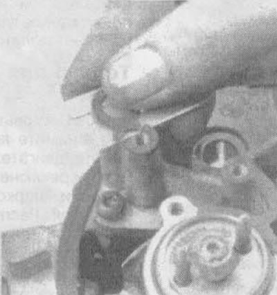
12.6. Carefully remove the fuel flow meter outlet gasket and cover gasket using a blade
Caution: Do not attempt to reuse any of these pads.
7. Inspect the cover for dirt, foreign bodies and deformation of the casting. If there is dirt, clean the cover with a clean cloth soaked in solvent. Do not immerse the fuel gauge cap in cleaning solvent; this can damage the pressure regulator diaphragm and gasket.
Caution! Do not remove the four screws (see illustration), pressing the pressure regulator against the fuel supply meter cover. The regulator contains a large compressed spring which, if accidentally released, could cause injury. Disassembling this assembly may also result in fuel leakage between the diaphragm and the regulator body. The new fuel gauge cover assembly includes a new pressure regulator.
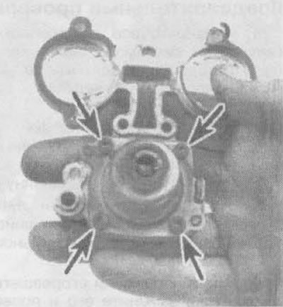
12.7 Never loosen the four pressure regulator screws (marked with arrows) from the fuel gauge cover
8. Install the new pressure regulator seal, fuel flow meter outlet gasket and cover gasket.
9. Install the meter cover using Loctite 262 (or similar) for screws.
Note: The short screws are tightened after the injectors are installed.
10. Connect the wiring connectors to both injectors.
11. Connect the wires to the battery.
12. With the engine off and the ignition on, check for leaks on the gaskets and connections of the fuel line.
13. Install the air filter and gaskets.