


Note: Broken valve springs and damaged valve stem seals can be replaced without removing the cylinder head. This operation typically requires two special tools and a source of compressed air, so review this section carefully and borrow or purchase the necessary equipment before beginning. If you do not have a source of compressed air, use a piece of nylon cord to prevent the valves from falling into the cylinder during operation.
1. Remove the valve cover from the corresponding cylinder head. If all valve seals are to be replaced, remove both valve covers (see section 4).
2. Remove the spark plug from the cylinder. If it is necessary to replace the seals on all valve stems, remove the spark plugs from all cylinders.
3. Turning the crankshaft, set the piston to the TDC position on the compression stroke (see section 3). If you are replacing the seals on all the valve stems, start with the 1st cylinder and continue replacing them on the others one by one. Move from one cylinder to another, observing the sequence of their operation (see technical data).
4. Screw the adapter into the spark plug hole (see illustration) and connect a hose from a compressed air cylinder to it.
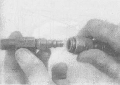
6.4. This is what the adapter to the air hose looks like, which is screwed into the hole for the spark plug
Note: Most compression testers come with a screw-on adapter that fits into the quick-release end of the air hose.
5. Loosen the bolt, remove the support and valve rocker arm and remove the push rod (see section 5). If it is necessary to replace the seals on all valve stems, then all valve rocker arms and valve push rods must also be replaced at the same time.
6. Direct a stream of compressed air into the cylinder. The valves should be held in place by air pressure. If the valve surfaces or seats are in poor condition, the valves may not stay in place due to air leakage. In this case, see. the procedure described below.
7. If there is no source of compressed air, another method can be used. Set the piston to a point about 45° short of TDC on the compression stroke, then push the end of a long nylon cord into the spark plug hole until it fills the combustion chamber. The other end of the cord must remain outside the engine, otherwise it will be difficult to reach. Using a socket wrench, turn the crankshaft in the direction of rotation until you feel slight resistance to turning.
8. Stuff rags into the cylinder head holes above and below the valves to prevent parts from falling out, and compress the valve spring using a special tool. Using pliers or a magnet, remove the spring crackers (see illustration).
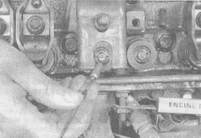
6.8. After compressing the valve spring, remove the crackers with a magnet (as shown) or pliers
Note: There are two types of devices for compressing valve springs with the cylinder head on. One of them works on the principle of gripping the lower spring rings and pressing on the spring plate when turning the handle. The second device is a lever type; here the valve rocker arm bolt is used as a stop (see illustration). Both devices are quite effective.
9. After removing the spring crackers and valve spring, remove the cuff (see illustration).
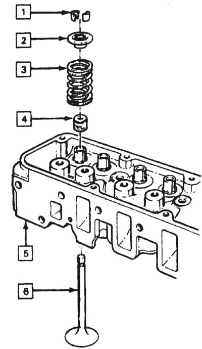
6.9 Valve details: 1 - valve rod crackers, 2 - valve spring plate, 3 - valve spring, 4 - valve guide cuff, 5 - cylinder head, 6 - valve
Note: If the air flow is not strong enough to hold the valves closed during this operation, the valve seat or face may be damaged. In this case, the cylinder head should be removed to perform additional repair work.
10. Wrap a rubber band around the top of the valve stem to prevent the valve from falling into the combustion chamber, then release the air pressure.
Note: If a nylon cord rather than compressed air was used, turn the crankshaft slightly in the opposite direction to normal rotation.
11. Check the valve stem for damage. By turning the valve in the guide, check it for eccentricity. The presence of eccentricity may indicate that the valve stem is bent.
12. Move the valve up and down in the guide to check if it is sticking. The presence of sticking means that either the valve stem is bent or its guide is damaged. In both cases, the cylinder head will have to be removed to perform additional repair work.
13. Blow compressed air into the cylinder again to hold the valve closed and remove the rubber band from the valve stem. If you used a nylon cord instead of an air jet, turn the crankshaft in the working direction of rotation until a slight resistance to rotation appears.
14. Apply a coat of engine oil to the valve stem and install a new valve guide seal.
15. Place the spring on top of the valve.
16. Install the spring retainer and compress the valve spring.
17. Place the crackers in the top groove. To prevent them from falling out during assembly, put a small amount of grease in them (see illustration). Release the pressure of the device on the spring, make sure that the spring crackers are in place.
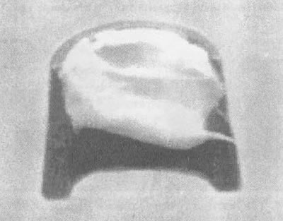
6.17. Before installation, apply a drop of grease to each cracker as shown here; this will hold them in place when installing the spring
18. Disconnect the air hose and unscrew the adapter from the spark plug hole. If a nylon cord was used instead of compressed air to perform these tasks, remove it from the cylinder.
19. Install the valve rocker arm and valve push rod.
20. Screw in the spark plugs and connect the spark wires to them.
21. Install the valve cover in accordance with section 4.
22. Start the engine and let it run for a while, then check for oil leaks or unusual noises coming from the valve cover area.