


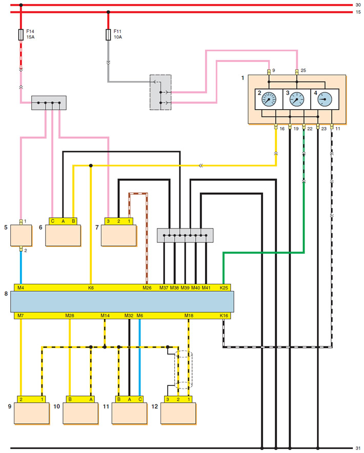
Engine control system diagram (start): 1 - instrument cluster; 2 - speedometer; 3 - tachometer; 4 - fuel level indicator; 5 - purge valve of the adsorber; 6 - vehicle speed sensor; 7 - phase sensor; 8 - Electronic engine control unit (ECU); 9 - intake manifold air temperature sensor; 10 - coolant temperature sensor; 11 - throttle position sensor; 12 - knock sensor
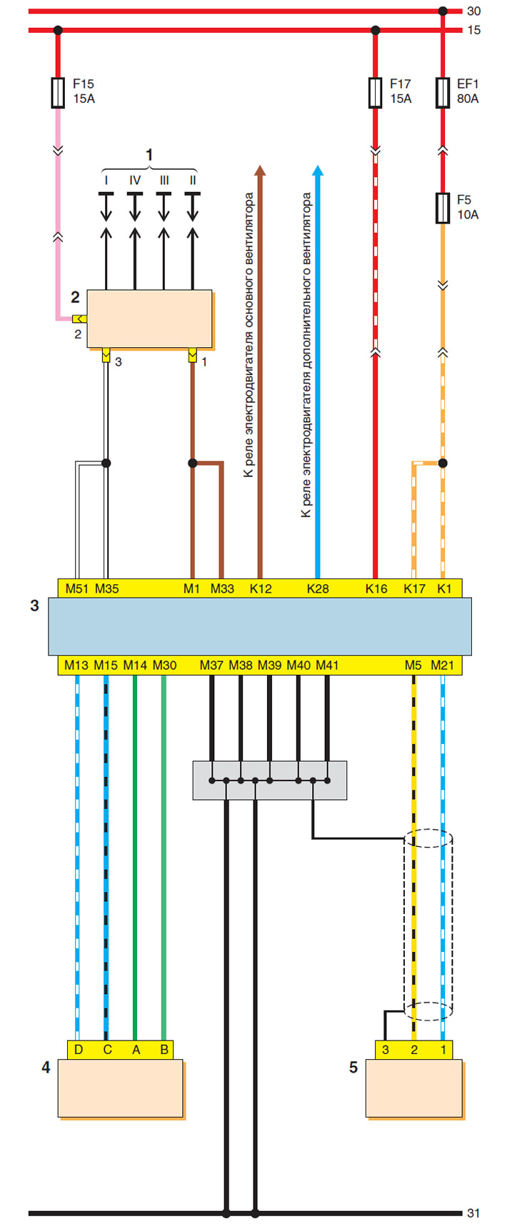
Engine Management System Diagram (continuation): 1 - spark plugs; 2 - ignition coil; 3 - ECU; 4 - idle speed controller; 5 - crankshaft position sensor

Engine Management System Diagram (continuation): 1 - fuel pump relay; 2 - injectors; 3 - ECU; 4 - exhaust gas recirculation valve; 5 - absolute air pressure sensor in the intake manifold; 6 - fuel pump
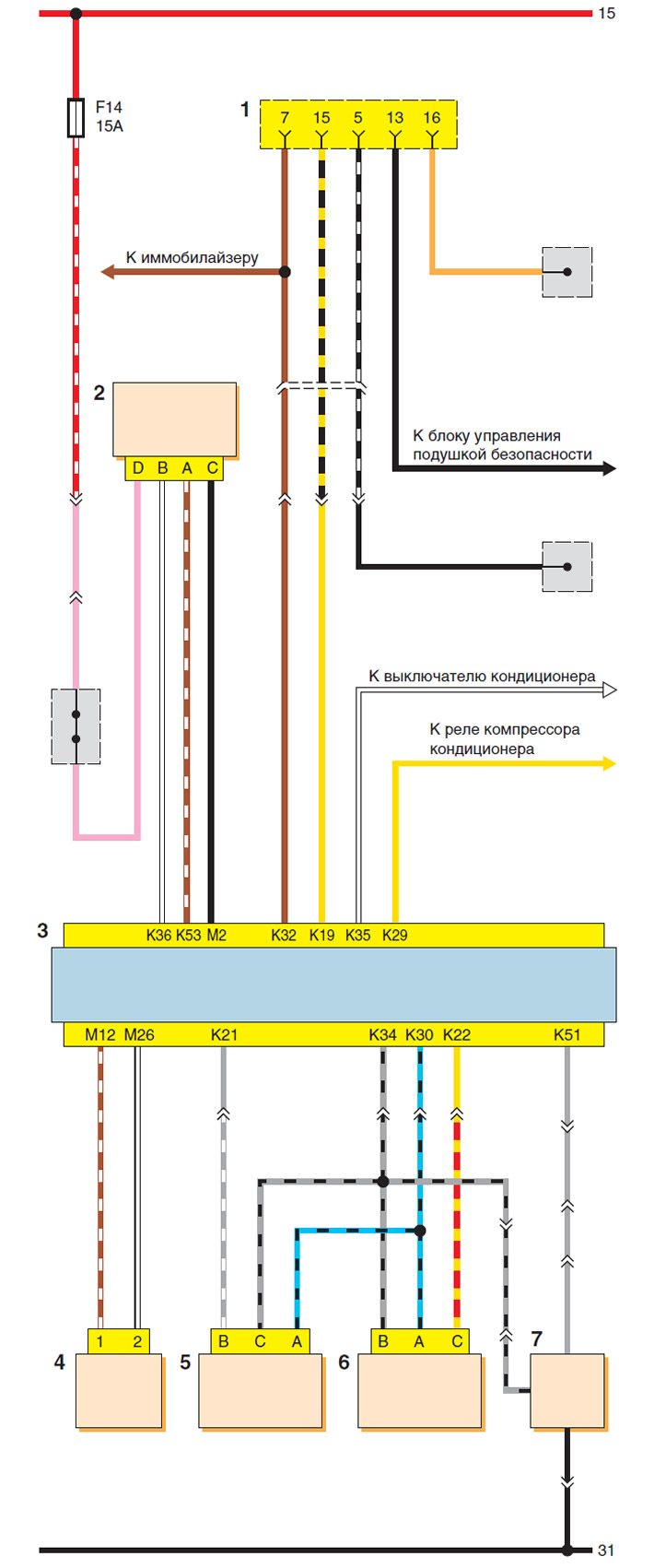
Engine control system diagram (end): 1 - diagnostic socket; 2 - diagnostic oxygen concentration sensor; 3 - ECU; 4 - oxygen concentration control sensor; 5 - Rough road sensor; 6 - refrigerant pressure sensor in the air conditioning system; 7 - fuel level indicator sensor
The original article can be found on the resource: «chevyman.ru»