Prepare and apply the SAP device 000017504553-00-00 according to the instructions for use (figure 8-144), onto the body sill and align it with the lower flange as shown in Figure 8-143. Secure the device to the body with adhesive tape, ensuring a tight fit to the body surface.
Attention: it is not allowed to use the device with defects that affect the accuracy of marking.
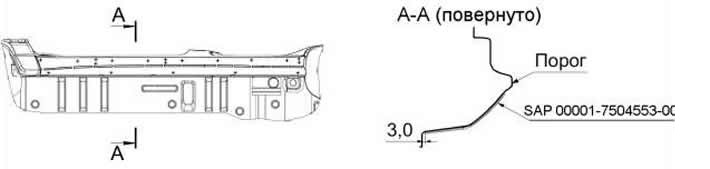
Figure 8-144. Left side threshold (bottom view).
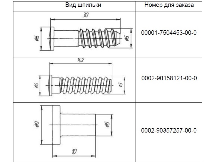
Weld the studs (Table 1) perpendicular to the plane of the threshold according to the markings with three welding points approximately 120 degrees apart around the circumference of the stud support area according to the diagram, Figure 8-145.
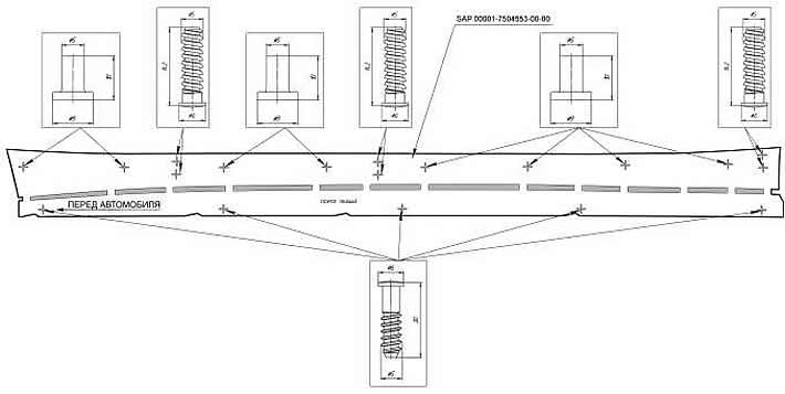
Figure 8-145. Layout of stud welding points using the fixture.
Table 1.