


Checking the condition of the clutch pressure plate assembly. Fasten the pressure plate 3 (figure 3-4) assembled with pressure spring 1 and casing 2 on a device with intermediate ring 4 of thickness B= (8.3+0.01) mm. This device replaces the flywheel with the driven disk.
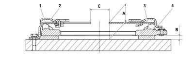
Figure 3-4. Clutch control:
1 - pressure spring;
2 - clutch housing;
3 - pressure plate;
4 - intermediate ring;
A, B, C - dimensions.
Perform a check by disengaging the clutch three times with a disengagement stroke of 8-9 mm, applying a load to the petals of the pressure spring 1 at a diameter of C=34 mm. In this case:
- check that the disengagement stroke (8.0+0.1) mm corresponds to a pressure plate stroke of at least 1.4 mm;
- the difference in the values of the pressure plate 3 offset is no more than 0.25 mm;
- size A should be within (35.7+1) mm;
- the load on the petals of the pressure spring 1 at diameter C with a stroke of (8.0+0.1) mm should be no more than 1330 N, the peak load of the switch-off should be no more than 1720 N.
Measure the depth of the annular wear of the pressure spring petals at the point of contact with the clutch release bearing; if the wear value exceeds 0.8 mm, replace the clutch housing assembly with the pressure plate.
[The article was reprinted from the website «ChevyMan»]