


Disconnect the wire terminal from the negative terminal of the battery. Remove the lower instrument panel trim (see Removal the lower instrument panel trim).
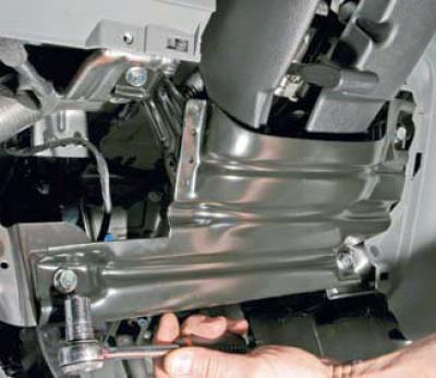
Using a 12 mm socket head, unscrew the four bolts securing the protective casing to the frame
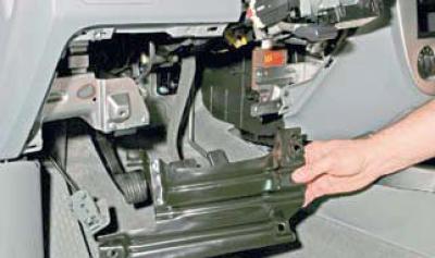
We remove the protective cover.
Remove the steering column switches and their connector (see Removal the steering column paddle shifters, coil cable drum and switch connector). Remove the glove box (see Removal the glove compartment). Remove the front part of the floor tunnel lining (see Removal the front section of the floor tunnel lining). Remove the central trim panel of the instrument panel with the control unit of the heating, ventilation and air conditioning system, as well as the hazard warning switch (see Removal the heating, ventilation and air conditioning control unit). Remove the head unit of the audio system and the storage compartment underneath it (see Removal the head unit of the audio system). Remove the steering column (see Removal the steering column). You don't have to dismantle the steering column completely, but just unscrew the bolts and nuts that secure its bracket to the body, and, without disconnecting the intermediate shaft, place the column on the floor.
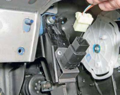
By pressing the lock, we disconnect the instrument panel harness connector from the brake light switch.
Also, having released the clamps, we disconnect the wiring harness pads from
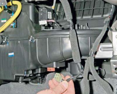
electronic speed controller for the electric motor of the fan of the heating and ventilation system
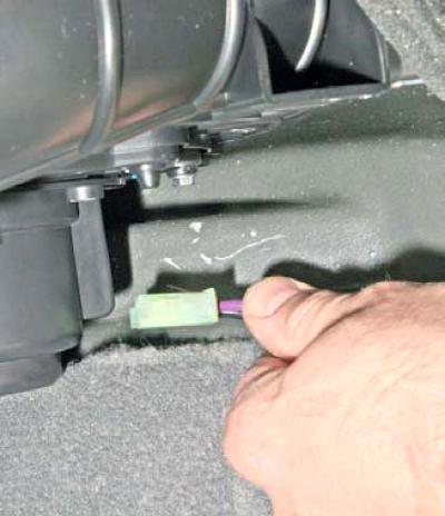
the electric motor itself
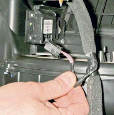
and electric drive of the recirculation flap.
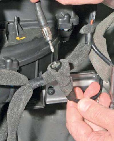
We disconnect the plug and socket of the antenna cable of the head unit of the audio reproduction system.
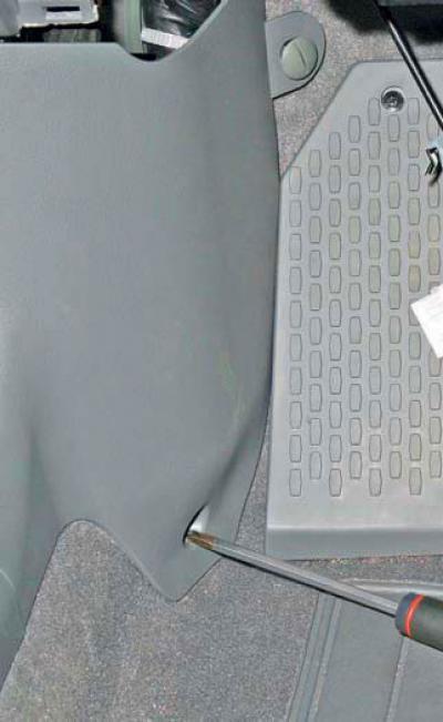
Using a Phillips screwdriver, unscrew the screw of the lower fastening of the left side panel, and using a slotted screwdriver, unscrew the plastic nut of the upper fastening.
We remove the left side panel trim.
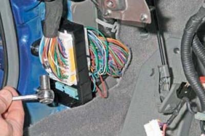
Using a 10 mm socket head, unscrew the bolt securing the instrument panel wiring harness connector to the vehicle's front wiring harness.
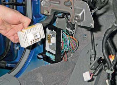
Disconnect the instrument panel wiring harness connector.
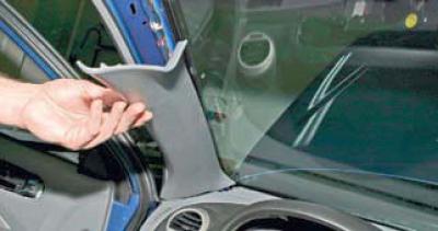
Overcoming the resistance of the clamps, we remove the trim of the left front pillar.
Similarly, we remove the trim of the right front pillar.
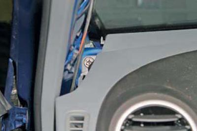
Using a 10 mm socket with an extension, unscrew the upper instrument panel mounting bolt on the left.
Similarly, unscrew the bolt of the upper fastening of the instrument panel on the right.
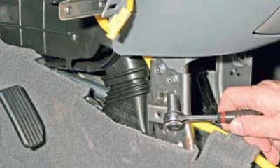
Using a 10 mm head, unscrew the two bolts of the lower mounting of the instrument panel on the left.
Similarly, unscrew the two bolts of the lower fastening of the instrument panel on the right.
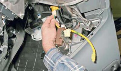
Disconnect the airbag wiring harness connector from the instrument panel wiring harness connector.
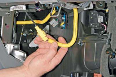
Release the front passenger airbag wiring harness connector from the holder and
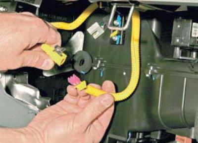
having released the lock, we disconnect the pads of the airbag wiring harness and the airbag wires.
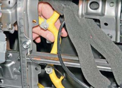
Release the two airbag wiring harness fasteners.
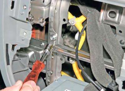
Using a 10 mm socket head, unscrew the bolt securing the terminal of the ground wire of the airbag wiring harness to the instrument panel frame.
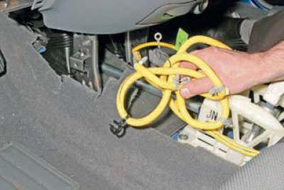
We remove the airbag wiring harness from the instrument panel cavity.
We disconnect the metal frame of the instrument panel from the heater body.
To do this, use a Phillips screwdriver to unscrew the screw..
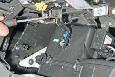
…under the front passenger airbag
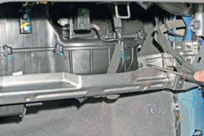
at the right edge of the heater body
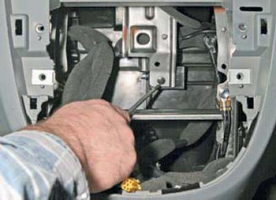
and in the cavity where the main unit of the sound reproduction system was located.
Next, we disconnect the power mount of the instrument panel frame from the body.
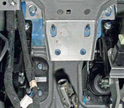
Using a 12 mm socket with an extension, unscrew the two bolts securing the instrument panel frame to the body in the area of the steering column.
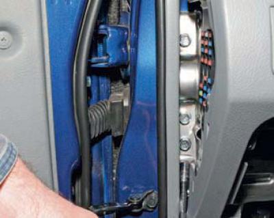
We open the cover of the fuse box in the passenger compartment and, using a 13 mm socket with an extension, unscrew the three bolts securing the instrument panel frame to the body.
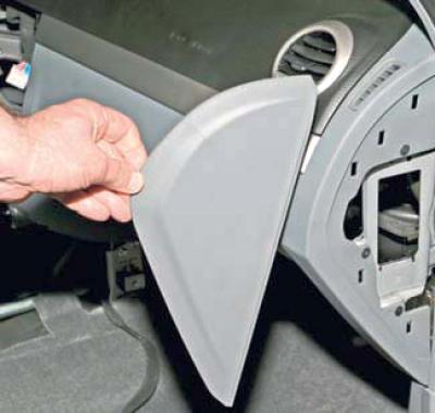
We open the instrument panel cover on the right… …and unscrew the three bolts of the right instrument panel frame mount.
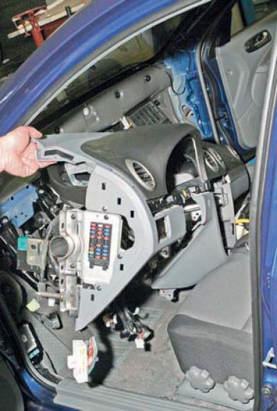
We remove the instrument panel together with the frame through the doorway.
You can separate the plastic trim and the metal frame of the instrument panel by unscrewing
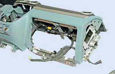
three side mounting screws on each side..
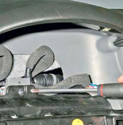
...one screw in the recess of the instrument cluster..
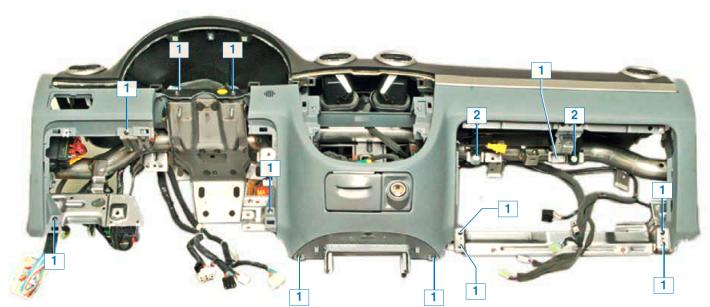
…twelve screws 1 and two bolts 2
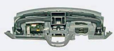
and one self-tapping screw installed on the back side of the instrument panel.
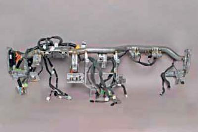
Instrument cluster frame with wiring harness
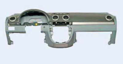
Plastic trim for the instrument panel
We install the instrument panel in the reverse order.
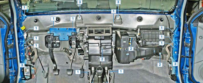
Instrument cluster frame mounting points (the instrument panel has been removed): 1 - under bolts; 2 - for self-tapping screws; 3 - under the guide pins