


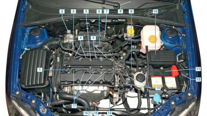
Elements of the electronic engine management system: 1 - phase sensor; 2 — idle speed control unit and throttle position sensor; 3** — coolant temperature sensor; 4 — injectors; 5**; - knock sensor; 6 - absolute air pressure sensor in the intake manifold; 7** — engine intake air temperature sensor; 8** — diagnostic socket; 9** — speed sensor; 10 - fuse and relay mounting block; 11 — battery; 12 — electronic control unit; 13 - ignition coils; 14** — crankshaft position sensor; 15 - oxygen concentration control sensor; 16** — diagnostic oxygen concentration sensor; 17** — spark plugs.
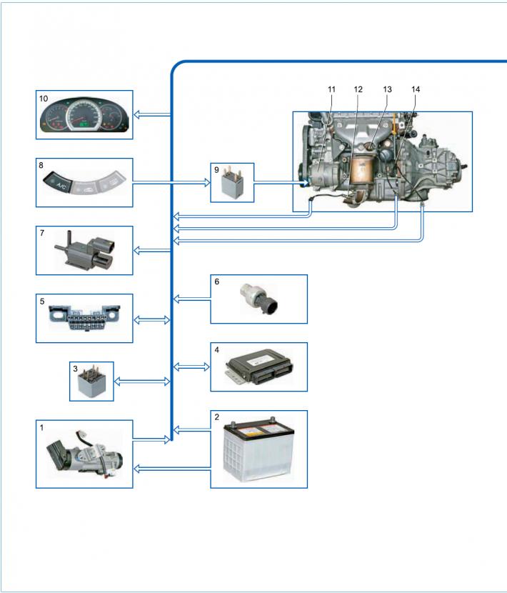
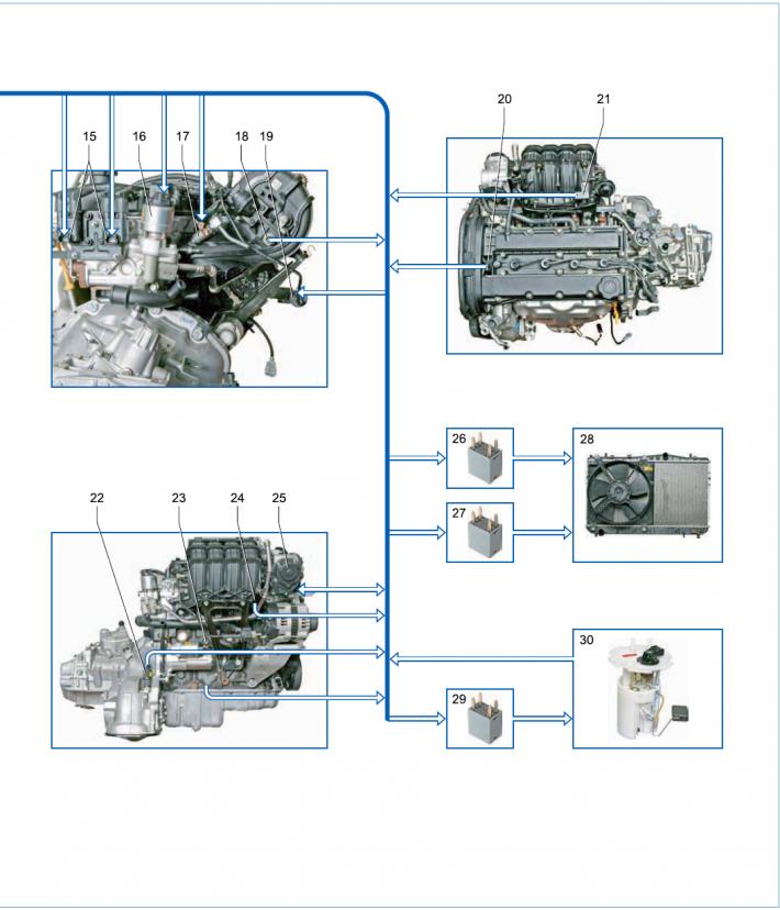
Electronic engine management system diagram: 1 - battery; 2 - ignition switch; 3 - main relay of the engine management system; 4 — ECU; 5 — diagnostic socket; 6 - air conditioner refrigerant pressure sensor; 7 — valve of the intake tract length variation system; 8 - air conditioner switch; 9 — air conditioning compressor relay; 10 — instrument cluster; 11 — air conditioning compressor; 12 - diagnostic oxygen concentration sensor; 13 - oxygen concentration control sensor; 14 — crankshaft position sensor; 15 - ignition coils; 16 — exhaust gas recirculation valve; 17 — nozzle; 18 — intake air temperature sensor; 19 — purge valve of the adsorber; 20 — phase sensor; 21 — absolute air pressure sensor in the intake manifold; 22 - vehicle speed sensor; 23 - knock sensor; 24 - coolant temperature sensor; 25 — Idle speed control unit and throttle position sensor; 26 - High speed cooling fan relay; 27 — Low speed cooling fan relay; 28 — cooling system fan; 29 — fuel pump and ignition coil relay; 30 — fuel module.
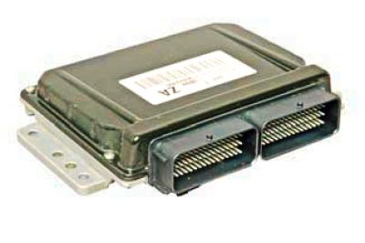
Electronic engine control unit.
The engine is equipped with a distributed phased fuel injection system: gasoline is supplied by injectors to each cylinder in turn in accordance with the engine operating order.
The engine management system consists of an electronic control unit (ECU), sensors for engine and vehicle operating parameters, and actuators.
The ECU is a special-purpose mini-computer. It consists of a random access memory (RAM) and a programmable read-only memory (PROM).
The ECU is located in the engine compartment - it is attached to the left mudguard with a bracket. In addition to supplying power to the sensors and controlling the actuators, the ECU performs diagnostic functions of the engine management system (on-board diagnostic system) — determines the presence of faults in the elements of the system, turns on the fault indicator in the instrument cluster and stores fault codes in its memory. When a fault is detected, in order to avoid negative consequences (burnout of pistons due to detonation, damage to the catalytic converter in the event of misfires of the fuel-air mixture, exceeding the toxicity limits of exhaust gases, etc.), The ECU switches the system to emergency operating modes.
Their essence is that when any sensor or its circuit fails, the engine control unit uses replacement data stored in its memory.
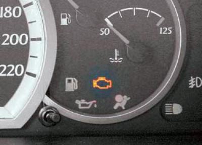
The engine management system malfunction indicator is located in the instrument cluster.
If the system is working properly, then when the ignition is turned on, the indicator should light up - thus, the ECU checks the serviceability of the indicator and the control circuit.
After starting the engine, the indicator should go out if there are no conditions for its activation in the ECU memory. When the indicator is activated while the engine is running, it informs the driver that the on-board diagnostic system has detected a malfunction and further movement of the car occurs in emergency mode.
This may worsen some engine performance parameters (power, responsiveness, economy), but driving with such faults is possible, and the car can drive to the service station on its own.
If the fault is temporary, the electronic control unit will turn off the indicator after three fault-free trips.
Error codes (even if the indicator goes out) remain in the unit's memory and can be read using a special diagnostic device – a scanner connected to the diagnostic connector.
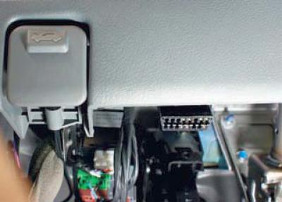
Diagnostic connector
Diagnostic connector (diagnostic connector) located under the instrument panel - attached with two screws to the instrument panel frame bracket (slightly to the right of the hood lock handle).
When the fault codes are cleared from the electronic unit memory using the diagnostic tool, the fault indicator in the instrument cluster goes out.
The control system sensors provide the ECU with information about the engine and vehicle operating parameters, based on which it calculates the moment, duration and order of opening of the fuel injectors, the moment and order of spark formation.
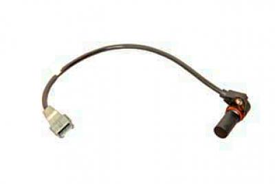
Crankshaft position sensor
The crankshaft position sensor is located on the front wall of the cylinder block under the oil filter.
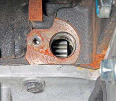
The sensor provides the controller with information about the rotation speed and angular position of the crankshaft.
The sensor is an inductive type, reacting to the passage of the teeth of the setting disk near its core, attached to the cheek of the crankshaft of the 4th cylinder. The teeth are located on the disk at an interval of 6°. To determine the position of the crankshaft, two teeth out of 60 are cut off, forming a wide groove.
When this groove passes the sensor, a so-called "reference" synchronization pulse is generated in it. The installation gap between the sensor core and the tops of the teeth is approximately 1.3 mm. When the reference disk rotates, the magnetic flux in the sensor's magnetic circuit changes - AC voltage pulses are induced in its winding. Based on the number and frequency of these pulses, the ECU calculates the phase and duration of the injector and ignition coil control pulses.
Phase sensor (camshaft position) attached to the right end of the cylinder head near the exhaust camshaft pulley.
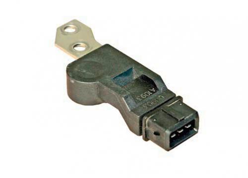
Phase sensor
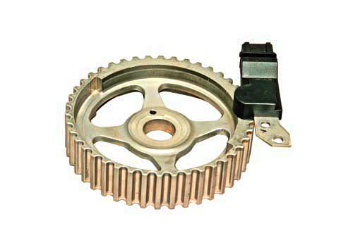
Relative position of the phase sensor and the exhaust camshaft pulley
The ECU uses the phase sensor signal to coordinate fuel injection processes in accordance with the cylinder firing order.
The operating principle of the sensor is based on the Hall effect.
The sensor reacts to the passage of a protrusion made on the end of the camshaft pulley to determine the position of the piston of the first cylinder during the working stroke. Depending on the angular position of the shaft, the sensor sends rectangular voltage pulses of different levels to the control unit. Based on the output signals of the crankshaft and camshaft position sensors, the control unit sets the ignition advance angle and the cylinder to which fuel should be supplied. If the phase sensor fails, the ECU switches to the unphased fuel injection mode.
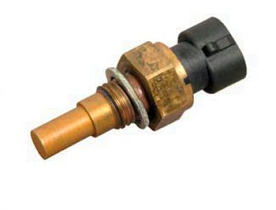
The coolant temperature sensor is screwed into a threaded hole in the rear wall of the cylinder head, between the air supply channels of the 1st and 2nd cylinders. The sensor rod is washed by the coolant circulating through the cooling jacket of the cylinder head.
The sensor is a thermistor with a negative temperature coefficient, i.e. its resistance decreases with increasing temperature. The ECU supplies the sensor with a stabilized voltage of +5.0 V through the resistor and, based on the voltage drop on the sensor, calculates the coolant temperature, the values of which are used to adjust the fuel supply and ignition timing.
The throttle position sensor is mounted on the throttle shaft and is a potentiometric type resistor.
A stabilized voltage of +5.0 V is supplied to one end of its resistive element from the ECU, and the other is connected to the "ground" of the electronic unit. A signal for the control unit is taken from the third output of the potentiometer (slider), which is connected to the throttle axis. By periodically measuring the output voltage of the sensor signal, the ECU determines the current position of the throttle valve to calculate the ignition advance angle and the duration of the fuel injection pulses, as well as to control the idle speed controller. The throttle position sensor and the idle speed controller are combined into one unit, fixed on the throttle assembly.
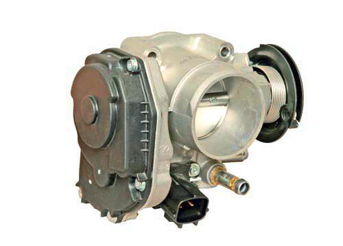
Location of the idle speed control unit and throttle position sensor on the throttle assembly
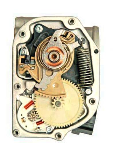
Idle Speed Control and Throttle Position Sensor Unit Components
If the sensor fails, it is necessary to replace the entire throttle assembly together with the idle speed control unit and the throttle position sensor (see Removal the throttle assembly).
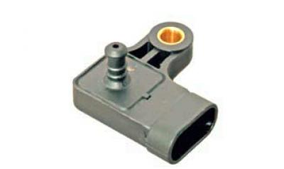
Absolute pressure sensor (rarefaction) the air pressure sensor in the intake manifold is attached to the intake manifold body and connected by a tube to its receiver. The sensor evaluates changes in air pressure in the intake manifold, which depend on the engine load and the rotation speed of its crankshaft, and converts them into output voltage signals. Based on these signals, the ECU determines the amount of air entering the engine and calculates the required amount of fuel. To supply more fuel at a large throttle opening angle (the vacuum in the intake manifold is insignificant) The ECU increases the operating time of the fuel injectors.
When the throttle opening angle decreases, the vacuum in the intake manifold increases, and the ECU, processing the signal, reduces the operating time of the injectors. The absolute air pressure sensor in the intake manifold allows the ECU to make adjustments to the engine operation when the atmospheric pressure changes depending on the altitude above sea level.
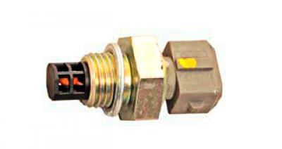
The intake air temperature sensor is screwed into the threaded hole of the intake manifold receiver. The sensor is a thermistor (with the same electrical characteristics as the coolant temperature sensor), which changes its resistance depending on the air temperature. The ECU supplies a stabilized voltage of +5.0 to the sensor via a resistor and measures the change in the signal level to determine the intake air temperature.
The signal level is high when the air in the pipeline is cold and low when the air is hot.
The ECU takes into account the information received from the sensor when calculating the air flow to correct the fuel supply and ignition timing.
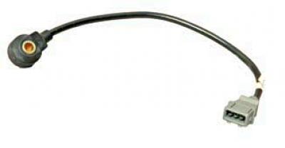
The knock sensor is attached to the rear wall of the cylinder block in the area of the 3rd cylinder.
The piezoelectric sensitive element of the sensor generates an alternating voltage signal, the amplitude and frequency of which correspond to the parameters of the engine block wall vibrations. When detonation occurs, the amplitude of vibrations of a certain frequency increases. At the same time, to suppress detonation, the ECU adjusts the ignition advance angle towards a later one.
The engine management system uses two oxygen concentration sensors: a control sensor and a diagnostic sensor.
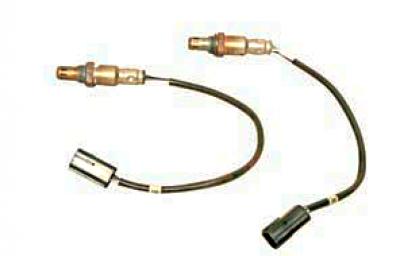
Oxygen concentration sensors: control and diagnostic
The oxygen concentration control sensor is installed in the exhaust manifold.
The sensor is a galvanic current source, the output voltage of which depends on the oxygen concentration in the environment surrounding the sensor. Based on the signal from the sensor about the presence of oxygen in the exhaust gases, the ECU adjusts the fuel supply by the injectors so that the composition of the working mixture is optimal for the efficient operation of the catalytic converter of the exhaust gases.
Oxygen contained in the exhaust gases, after entering into a chemical reaction with the sensor electrodes, creates a potential difference at the sensor output, varying from approximately 0.1 V to 0.9 V.
Low signal level corresponds to a lean mixture (presence of oxygen), and a high level is rich (oxygen is absent). When the sensor is in a cold state, there is no output signal from the sensor, since its internal resistance in this state is very high - several MOhms (the engine management system operates in open loop).
For normal operation, the oxygen concentration sensor must have a temperature of at least 300°C.
In order to quickly warm up the sensor after starting the engine, a heating element is built into the sensor, which is controlled by the ECU. As it warms up, the resistance of the sensor drops, and it begins to generate an output signal. Then the ECU begins to take into account the signal from the oxygen concentration sensor to control the fuel supply in closed-loop mode.
The oxygen sensor may be "poisoned" by using leaded gasoline or by using sealants containing large amounts of silicone during engine assembly (silicon compounds) with high volatility. Silicone vapors can enter the engine combustion chamber through the crankcase ventilation system. The presence of lead or silicon compounds in the exhaust gases can cause the sensor to fail.
In the event of failure of the sensor or its circuits, the ECU controls the fuel supply in an open circuit.
The oxygen concentration diagnostic sensor is installed after the catalytic converter in the intermediate pipe of the exhaust system. The main function of the sensor is to evaluate the efficiency of the catalytic converter.
The signal generated by the sensor indicates the presence of oxygen in the exhaust gases after the catalytic converter. If the catalytic converter is working properly, the diagnostic sensor readings will differ significantly from the control sensor readings.
The operating principle of the diagnostic sensor is the same as that of the control oxygen concentration sensor.
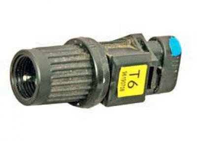
The vehicle speed sensor is mounted on the top of the gearbox clutch housing, next to the gear shift mechanism.
The operating principle of the speed sensor is based on the Hall effect.
The sensor drive gear is engaged with the gear mounted on the differential box. The sensor sends rectangular voltage pulses to the ECU with a frequency proportional to the rotation speed of the drive wheels. The number of sensor pulses is proportional to the distance traveled by the vehicle.
The ECU determines the vehicle speed based on the pulse frequency.
The ignition system is part of the engine management system and consists of two ignition coils, high-voltage wires and spark plugs. In operation, the system does not require maintenance or adjustment, except for replacing the spark plugs.
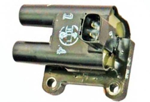
The current in the primary windings of the coils is controlled by an electronic unit depending on the engine operating mode.
To the conclusions of secondary (high voltage) spark plug wires are connected to the coil windings: to one coil - the 1st and 4th cylinders, to the other - the 2nd and 3rd. Thus, a spark simultaneously jumps in two cylinders (1-4 or 2-3) - in one at the end of the compression stroke (working spark), in the other - at the end of the exhaust stroke (idle).
The ignition coil is non-separable and is replaced when it fails.
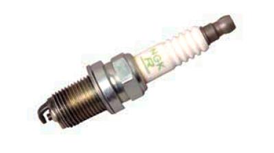
Spark plugs NGK BKR6 E-11 (1.4L and 1.6L engines) and NGK BKUR6ETB (1.8L engine) or similar products from other manufacturers.
The gap between the spark plug electrodes is 1.0–1.1 mm (1.4L and 1.6L engines) and 0.7–0.9 mm (1.8L engine).
The spark plug hexagon size is for a 16 mm socket.
When the ignition is turned on, the ECU powers the fuel pump relay for 2 seconds to create the required pressure in the fuel rail. If the crankshaft has not been turned by the starter during this time, the ECU switches off the relay and switches it on again after cranking has begun.
If the engine has just been started and its speed is above 400 min¯¹, the control system operates in an open loop, not taking into account the signal from the control oxygen concentration sensor. In this case, the ECU calculates the composition of the air-fuel mixture based on the incoming signals from the coolant temperature sensor and the absolute air pressure sensor in the intake manifold. After the control oxygen concentration sensor has warmed up, the system begins to operate in a closed loop, taking into account the sensor signal.
If the engine does not start when trying to start it and there is a suspicion that the cylinders are flooded with excess fuel, they can be blown out by fully pressing the gas pedal and turning on the starter. With this position of the throttle valve and crankshaft speed below 400 min¯¹, the ECU will turn off the injectors. When releasing the gas pedal, when the throttle valve is open less than 80%, the ECU will turn on the injectors.
When the engine is running, depending on the information coming from the sensors, the mixture composition is regulated by the duration of the control pulse supplied to the injectors (the longer the pulse, the more fuel is supplied).
During engine braking (with the gear and clutch engaged), when the throttle valve is fully closed and the engine speed is high, fuel injection is not performed to reduce exhaust toxicity.
When the voltage in the vehicle's on-board network drops, the ECU increases the time it takes for the energy to accumulate in the ignition coils (for reliable ignition of the combustible mixture) and injection pulse duration (to compensate for the increase in the injector opening time). As the voltage in the on-board network increases, the time it takes for energy to accumulate in the ignition coils and the duration of the pulse supplied to the injectors decreases.
When the ignition is turned off, the fuel supply is cut off, which prevents spontaneous combustion of the mixture in the engine cylinders.
When servicing and repairing the engine management system, always turn off the ignition (in some cases, it is necessary to disconnect the wire terminal from the negative terminal of the battery). When carrying out welding work on the car, disconnect the wiring harnesses of the engine management system from the ECU. Before drying the car in a drying chamber (after painting) remove the ECU.
With the engine running, do not disconnect or adjust the engine management system wiring harness connectors or the battery terminal wire terminals. Do not start the engine if the battery terminal wire terminals and the engine ground wire terminals are loose or dirty.
The material was created based on information from the website: chevyman.ru