
Contents: The crankshaft turns but the engine… ↧ Fuel Rail Pressure Regulator… ↧ Fuel Pump Electrical Circuit… ↧ Fuel system diagnostics ↧ Fuel return system diagnostics ↧ Fuel leaks ↧ Checking the injector balance with a… ↧ Diagnostics of contaminants in fuel ↧ Removal water from the fuel system ↧ Removal gasoline from the fuel system ↧ Fuel heater not working ↧ Data Channel Messages ↧ The scanning device does not turn on ↧ The scan tool does not communicate… ↧ Scan tool does not communicate with… ↧ Programming and initial installation… ↧ Diesel Particulate Filter (DPF)… ↧
The crankshaft turns but the engine does not start
Description of the scheme
The diagnostic table "Crankshaft turns, but the engine does not start" systematizes the method of identifying a malfunction that prevents the engine from starting. The diagnostic table "Crankshaft turns, but the engine does not start" contains instructions for a service center specialist to perform the appropriate diagnostics of the systems.
The "Crankshaft Cranks But Engine Does Not Start" diagnostic chart assumes that the following conditions are met:
- The batteries are fully charged.
- The crankshaft speed when starting the engine meets technical requirements.
- There is sufficient fuel in the fuel tanks.
Diagnostic information
If the cause of the malfunction "The crankshaft turns but the engine does not start" is not found, check for the following malfunctions:
Difficult starting only at low ambient temperatures. This may be due to an intermittent fault that does not occur in the service center:
- Fuel heater not working
- Ice blockage of the fuel pickup in the fuel tank. This fault will cause a vacuum to build up in the feed lines when the engine is started and will disappear when the vehicle is in the workshop. It may also manifest as a "start and stop" fault or a no-start fault.
- Water or foreign matter in the fuel system
- General engine failure
Description of the test
The number below refers to the step numbers from the diagnostic table.
5. This step checks to see if ignition 1 voltage is supplied to the ECM.
7. In some cases, lack of compression, possibly due to excessive fuel delivery, in any one cylinder can cause the engine not to start.
The crankshaft turns but the engine does not start
| Step | Operation | Values | Yes | No |
| 1 |
Have you performed a diagnostic system check?
|
-
|
Jump to operations 2
|
Go to item "Checking the diagnostic system".
|
| 2 |
Are there any diagnostic trouble codes displayed on the scan tool for the fuel pressure regulator, fuel rail pressure (FRP) sensor, CKP sensor, CMP sensor, ECM internal error, 5V reference circuits, glow plug controller, or immobilizer fuel enable signal?
|
-
|
Jump to the appropriate diagnostic trouble code table
|
Jump to operations 3
|
| 3 |
Are there any customer complaints about fuel odor or leakage?
|
-
|
Go to section "Fuel leaks"
|
Jump to operations 4
|
| 4 |
Determine the value of the parameter "Actual fuel rail pressure" using a scanning device (Actual Fuel Rail Pressure).
Does the parameter have a set value?
|
0.5 V
|
Jump to operations 5
|
Jump to operations 10
|
| 5 |
Check the value of the parameter "Ignition signal 1" using a scan tool (Ignition 1 signal)
Does the "Ignition Signal 1" parameter have a set value?
|
0.5 V
|
Jump to operations 6
|
Jump to operations 13
|
| 6 |
Check the following:
Has the problem been detected and corrected?
|
-
|
Jump to operations 19
|
Jump to operations 7
|
| 7 |
Perform an engine compression test
Has the problem been detected and corrected?
|
-
|
Jump to operations 20
|
Jump to operations 8
|
| 8 |
Important: If there is a high resistance in the signal circuits or in the low reference voltage circuits of the crankshaft position sensor (CKP), the scanning device will display "Engine speed" for the parameter (Engine Speed) a value greater than 0. This will not be an accurate measurement of engine speed and may cause a "Crankshaft Cranks But Engine Does Not Start" type of fault.
Check for high resistance in the crankshaft position sensor signal circuits and low reference voltage.
Has the problem been detected and corrected?
|
-
|
Jump to operations 19
|
Jump to operations 9
|
| 9 |
Check the following:
Has the problem been detected and corrected?
|
-
|
Jump to operations 19
|
Go to Diagnostic Information
|
| 10 |
Is the value of the "Actual fuel rail pressure" parameter less than the set value?
|
-
|
Jump to operations 11
|
Jump to operations 12
|
| 11 |
Check if there is a short to ground in the fuel rail pressure sensor signal circuit.
Has the problem been detected and corrected?
|
-
|
Jump to operations 19
|
Jump to operations 16
|
| 12 |
Check for high resistance in the fuel rail pressure sensor signal circuits.
Has the problem been detected and corrected?
|
-
|
Jump to operations 19
|
Jump to operations 14
|
| 13 |
Has the problem been detected and corrected?
|
-
|
Jump to operations 19
|
Jump to operations 15
|
| 14 |
Check the fuel rail pressure sensor for an intermittent or poor connection.
Has the problem been detected and corrected?
|
-
|
Jump to operations 19
|
Jump to operations 17
|
| 15 |
Does the engine start?
|
-
|
Jump to operations 19
|
Jump to operations 16
|
| 16 |
Check the ECM for intermittent faults or poor connections.
Has the problem been detected and corrected?
|
-
|
Jump to operations 19
|
Jump to operations 18
|
| 17 |
Replace the fuel rail pressure sensor.
Has the replacement been made?
|
-
|
Jump to operations 19
|
-
|
| 18 |
Replace the ECM.
Has the replacement been made?
|
-
|
Jump to operations 19
|
-
|
| 19 |
Does the engine start and continue to run?
|
-
|
Jump to operations 20
|
Jump to operations 2
|
| 20 |
Are there any DTCs displayed on the display?
|
-
|
Jump to the appropriate diagnostic trouble code table
|
The system is normal
|
Fuel Rail Pressure Regulator Diagnostics
Plotting a fuel rail pressure regulator graph provides valuable information about the regulator's performance by comparing the desired and actual fuel rail pressures. Comparing the actual and desired fuel rail pressures gives a nearly ideal result for a relatively new engine with a short service life. Small pulsations are acceptable for a fuel rail pressure regulator and are present in engines with a long service life. Sharp pulsations in the actual fuel rail pressure indicate a jammed pressure regulator.
1. Start the engine and let it idle.
2. Check the graph plotted by the scan tool for any sudden changes or pulsations in the actual fuel pressure in the fuel rail while simultaneously performing the following actions:
- The engine is idling
- Shifting the gearbox from "Parking" to "Driving" and back to "Parking"
- Rotate the steering wheel from the left extreme position to the right extreme position.
- Turning the air conditioning on and off
7. If the graph shows strong fluctuations in the actual fuel rail pressure, similar to the sharp pulsations shown in the graph below, then the fuel pressure regulator needs to be replaced.
Chart for a working fuel pressure regulator; new engine with short service life
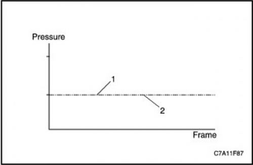
1. Actual fuel rail pressure
2. Required fuel rail pressure
Chart for a working fuel pressure regulator; long life engine
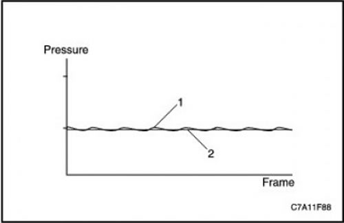
1. Actual fuel rail pressure
2. Required fuel rail pressure
Chart for a sticking fuel pressure regulator
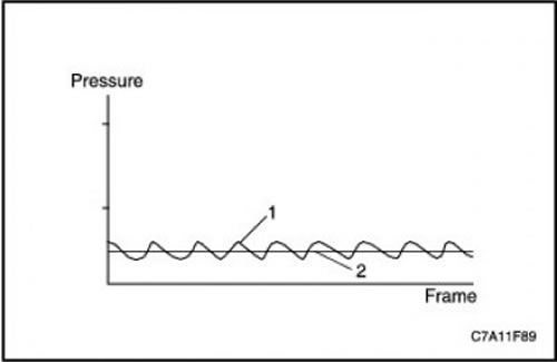
1. Actual fuel rail pressure
2. Required fuel rail pressure
Fuel Pump Electrical Circuit Diagnostics
Description of circuits/systems
The electric fuel pump is used to initially fill the fuel system after replacing the fuel filter or servicing the fuel system. Power is supplied to the fuel pump through the fuel pump relay. The fuel pump relay is controlled by the ECM. The ECM turns the fuel pump on when the ignition is turned on and will continue to control it for a short time or until the engine starts. If the ignition is left in the "on" position, the pump will run for about four seconds. In addition, the ECM turns the fuel pump OFF if it detects an abnormal voltage in the control circuit. The ECM will need to be turned off with the key during diagnostics or after repairs before it will command the fuel pump on again.
Diagnostic information
A blown fuel pump fuse may be caused by the following reasons:
- The fuse is faulty
- Intermittent short circuit to ground in the fuel pump voltage supply circuit
- Intermittent internal fuel pump failure
Circuit/System Testing
1. Check the fuel pump fuse.
2. If there is an open circuit in the fuel pump fuse, check whether there is a short circuit to ground in the positive circuit of the battery and the voltage supply circuit to the fuel pump, and whether the fuel pump is working properly.
3. Turn on the ignition with the engine off.
4. Command the fuel pump on and off with a scan tool. The fuel pump relay should click on and off with each command.
5. If the fuel pump operates continuously, check whether the relay is working properly and whether there is a short circuit to the live wire in the circuit supplying voltage to the fuel pump.
6. If the fuel pump does not turn on or off, replace the fuel pump relay.
7. Check the positive battery circuit at the fuel pump relay with a test light connected to a good ground connection.
8. If the test lamp does not light, eliminate the break in the positive terminal circuit of the battery.
9. Connect a jumper wire with a fuse between the positive battery terminal circuit and the voltage supply circuit to the fuel pump relay.
10. If the fuel pump is working, check to see if there is an intermittent fault or poor connection at the fuel pump relay and if the relay is working properly.
11. If the fuel pump does not work, check for an open or high resistance in the supply voltage circuit or in the ground connection circuit of the fuel pump.
12. If no faults are found when checking all circuits and the fuel pump relay is working properly, replace the fuel pump.
Fuel system diagnostics
Description of the fuel system
Fuel is taken by the pump through a strainer located in the fuel tank, located in front of the fuel filter, and fed to the engine through fuel pipelines. The fuel passes through the fuel filter / heater housing, which combines a water separator, a fuel heater heating element, and a filter element. The fuel is then fed to a high-pressure fuel pump designed for fuel injection. The output control function of the scanning device, or the repeated switching of the ignition key to the "on" / "off" positions, is used, after replacing the fuel filter or servicing the fuel system, to initially fill the fuel system by turning on the fuel pump when the engine is not running. If the fuel system does not supply enough fuel, the vehicle's handling may be affected. If air is sucked into the fuel injection system, there may be a sign of a malfunction such as "The crankshaft is turning, but the engine does not start" or "Difficult start".
High pressure system
The fuel injection pump is driven by the engine via the timing belt. From the high-pressure injection pump, fuel under pressure enters the common rail. The common rail delivers fuel under pressure to the fuel injectors. The common rail has a fuel rail pressure (FRP) sensor.
Fuel return system
The fuel return system takes fuel from the fuel injectors, common rail and fuel injection pump. The common rail has a fuel pressure regulator. The returned fuel goes into the fuel tank. If the fuel pressure on the high-pressure side of the system becomes excessive, the pressure regulator dumps fuel into the return system.
Diagnostic information
Air penetration into the fuel system can occur for the following reasons:
- Deformations or cuts in the sealing rings in the connections of the fuel supply lines
- Incorrectly installed fuel supply line fittings
- Porous or weathered rubber fuel supply lines
Circuit/System Testing
1. Disconnect the fuel supply line from the fuel injection pump.
2. Install a pressure gauge to measure the fuel pressure between the fuel injection pump inlet and the fuel supply line.
3. Perform initial filling of the fuel system.
4. Using a scan tool, turn on the fuel pump and read the fuel pressure gauge to determine if there is fuel pressure. Inspect the engine and chassis for leaks or damage to fuel hoses, fuel lines, and fuel system components.
- 5. Repair leaks or replace any components that are found to be damaged or leaking.
6. If the fuel pump did not work and there was no fuel pressure, then refer to the item "Diagnostics of the fuel pump electrical circuit".
7. If the fuel pump started but there was no fuel pressure, check for a vacuum leak in the fuel supply line.
8. If no leaks or damage are found in the fuel system, turn off the fuel pump and remove the fuel pressure gauge.
9. Install a transparent hose between the fuel injection pump inlet and the fuel supply line. Bend the hose into a vertical loop, where you can determine if there are air bubbles in the incoming fuel.
10. Using a scan tool, turn on the fuel pump and perform a primary fill of the fuel system, continuing to do so until all air is removed from the system. Start the engine and let it run for at least 10 minutes to allow the fuel system conditions to stabilize.
11. If you see air bubbles in the transparent hose, check for a leak in the fuel level sensor.
12. If air bubbles do not disappear after replacing the fuel level sensor, refer to the "Diagnostic information" section.
13. If after replacing the fuel level sensor the air bubbles disappear, remove the transparent hose and start the engine to make sure there are no fuel leaks.
Fuel return system diagnostics
Description of the fuel system
Fuel is taken by the pump through a strainer located in the fuel tank, located in front of the fuel filter, and fed to the engine through fuel pipelines. The fuel passes through the fuel filter / heater housing, which combines a water separator, a fuel heater heating element, and a filter element. The fuel is then fed to a high-pressure fuel pump designed for fuel injection. The output control function of the scanning device, or the repeated switching of the ignition key to the "on" / "off" positions, is used, after replacing the fuel filter or servicing the fuel system, to initially fill the fuel system by turning on the fuel pump when the engine is not running. If the fuel system does not supply enough fuel, the vehicle's handling may be affected. If air is sucked into the fuel injection system, there may be a sign of a malfunction such as" The crankshaft is turning, but the engine does not start "or"Difficult start".
High pressure system
The fuel injection pump is driven by the engine via the timing belt. From the high-pressure injection pump, fuel under pressure enters the common rail. The common rail delivers fuel under pressure to the fuel injectors. The common rail has a fuel rail pressure (FRP) sensor.
Fuel return system
The fuel return system takes fuel from the fuel injectors, common rail and fuel injection pump. The common rail has a fuel pressure regulator. The returned fuel goes into the fuel tank. If the fuel pressure on the high-pressure side of the system becomes excessive, the pressure regulator dumps fuel into the return system.
Diagnostic information
Bent or pinched engine fuel return lines can cause poor fuel return.
Fuel return system diagnostics
| Step | Operation | Values | Yes | No |
| 1 |
Important: Do not apply more air pressure to the return line than required.
Is air coming out through the filler pipe?
|
-
|
Jump to operations 6
|
Jump to operations 2
|
| 2 |
Is air coming out of the fuel return line?
|
-
|
Jump to operations 3
|
Jump to operations 4
|
| 3 |
Remove the fuel sensor unit
Has the replacement been made?
|
-
|
Jump to operations 6
|
-
|
| 4 |
Has the problem been detected and corrected?
|
-
|
Jump to operations 6
|
Jump to operations 5
|
| 5 |
Replace the fuel return line between the engine and the fuel tank.
Has the replacement been made?
|
-
|
Jump to operations 6
|
-
|
| 6 |
Has the problem been resolved?
|
-
|
The system is normal
|
Jump to the appropriate diagnostic trouble code table
|
Fuel leaks
1. Remove the air filter assembly.
2. Clean all fuel lines between the fuel injection pump and the fuel injectors using brake cleaner and dry.
3. Add 250 ml of oil dye to the fuel tank.
4. Start the engine and let it idle for 3-5 minutes.
- 5. Check for leaks around the fuel injection pump, fuel rail, and fuel injector feed lines. Tighten or replace leaking lines or components.
6. Fuel leakage may be caused by an obstruction to the fuel flow in the return fuel lines.
Checking the injector balance with a scan tool (cylinder compression test)
Description of the scheme
In the event of cylinder balance deviations from the norm, a scan tool test is available to localize the cause of the deviation. A compression test can be used to determine whether the cause is engine-related or injection-related. If the fault is found to be injector-related, further testing can determine which injector is causing the cylinder balance deviation.
The test includes 3 modes (A, B, C), which are used in different conditions.
Circuit/System Testing
Using a scan tool, perform a compression test following the instructions on the display.
Mode A: Determining the angular velocity for each of the cylinders during the compression test
Fuel injection to all injectors is disabled to perform a compression test using the starter without starting the engine. The engine speed is determined for each top dead center. A lower engine speed determined for any cylinder compared to the others indicates higher compression in that cylinder. The higher the engine speed determined for any cylinder, the lower the compression in that cylinder. In this test, the correction values used to control the fuel trim (FCB) are zero. Note that this test is designed to determine the comparative performance of each cylinder. The higher or lower compression reported here will not necessarily be obtained when determining the actual compression in the engine cylinders using a pressure gauge.
Mode B: Determining the quantitative correction for each of the cylinders
In this test mode, the engine operates using the correction values used to control fuel supply balancing (FCB). A quantitative correction is a correction value added to the amount of fuel injected to ensure that the engine vibration level is acceptable. The speed of rotation of the engine shaft for each of the cylinders is also determined. A higher balancing quantitative correction indicates that the injector takes longer to inject the amount of fuel that is needed to obtain the required engine torque.
Mode C: Determining angular velocities for each of the cylinders without using correction balancing values
In this test mode, the engine operates without using the correction values used for fuel trim control (FCB). It is possible to continuously determine the engine speed for each cylinder and the engine behavior during operation without using the FCB correction values.
Diagnostics of contaminants in fuel
Fungi and other microorganisms can survive and grow in diesel fuel if it contains water. Fungi can be found anywhere in the fuel system. These fungi grow as long filaments that then form large spherical particles. The growths are sticky and are usually black, green or brown in color. Fungi can grow anywhere in fuel, but they thrive where there is diesel fuel and water. Because the fuel is mixed when the tank is filled, the fungi are distributed throughout the tank and can be pumped into the vehicle. Fungi use fuel as their primary energy source and require only trace amounts of water and minerals. As they grow and multiply, they convert the fuel into water, sludge, acids and metabolic waste. The most common symptom is a clogged fuel filter, but corrosion of various metal parts of the fuel system can also occur, including the fuel level sensor, pipes, fuel injectors and the fuel injection pump.
CAUTION: To avoid personal injury, avoid physical contact with biocides.
If fungi have contaminated the fuel system, it is necessary to use biocides intended for diesel fuel to sterilize it. Do not exceed the dose indicated on the packaging. Use of biocide should be discontinued if a trailer is towed. The presence of biocide in the fuel is permissible at the start of towing, but biocide should not be added during the towing period.
If biocides cannot remove the majority of fungal growth, steam cleaning may be required.
The presence of water or gasoline in diesel fuel can also cause damage to the injection pump and fuel injectors.
The procedure described checks for the presence of water and gasoline in diesel fuel, which can cause damage to the injection pump and fuel injectors.
Remove and inspect the fuel filter.
- If there is no water, gasoline or fungi/bacteria, then finish the inspection.
- If there is water or fungi/bacteria, then proceed to the section "Removing water from the fuel system".
- If there is gasoline, then proceed to the section "Removing gasoline from the fuel system".
Removal water from the fuel system
1. Disconnect the negative battery cable.
2. Remove the sensor unit.
3. Inspect the fuel tank and fuel level sensor for corrosion, fungus or bacteria. If any components are found to be corroded, replace those components.
4. Rinse the inside of the fuel tank and the fuel level sensor with hot water.
5. Dry the fuel tank and fuel level sensor with compressed air.
6. Disconnect the ends of the following pipes:
- Fuel filter inlet pipe (both ends)
- Fuel filter outlet pipe (both ends)
- Fuel return line (both ends)
7. Inspect each tube and line.
8. Replace any pipes that are corroded.
9. Clean the inside of the fuel filter housing.
10. Dry the fuel filter housing with compressed air.
11. Dry each pipeline from the inside with low pressure air.
12. Remove ignition relay 1.
13. Install a new fuel filter.
14. Install the sensor unit.
15. Add clean diesel fuel to the main fuel tank until it is? full.
16. Connect the following pipelines:
- Fuel filter inlet pipe
- Fuel filter outlet pipe
- Fuel return line (to the fuel tank)
17. Connect the batteries.
18. Perform initial filling of the fuel system.
19. Connect the hose to the fuel return line at the engine and lower the other end into a 2-gallon (7.6 L) metal container.
20. Crank the engine in 30 second intervals with 1 minute rest periods for cooling. Continue until 3.8 liters (1 gallon) of fuel is in the container.
21. Connect the fuel return line.
22. Install ignition relay 1.
23. Start the engine.
24. Stop the engine.
25. Remove any fuel that has spilled from the engine.
26. Fill the tank with fuel and add biocide if necessary.
Removal gasoline from the fuel system
1. Drain the fuel from the tank.
2. Fill the fuel tank to?.
3. Remove ignition relay 1.
4. Open the fuel filter drain and connect a hose to the filter, the other end of which is lowered into a metal container.
5. Turn on the fuel pump using a scanning device and wait until clean fuel flows from the fuel filter into the container.
6. Close the fuel filter drain and disconnect the hose.
7. Connect the hose to the fuel return line at the engine and lower the other end into a 2-gallon (7.6 L) metal container.
8. Crank the engine in 30 second intervals with 1 minute rest periods for cooling. Continue until 3.8 liters (1 gallon) of fuel is in the container.
9. Connect the fuel return line.
10. Install ignition relay 1.
11. Try to start the engine and let it run for 15 minutes. If the engine does not start, perform the initial filling of the fuel system.
12. Stop the engine.
13. Remove any fuel that has spilled from the engine.
14. Clear all engine diagnostic trouble codes.
Fuel heater not working
Description of the scheme
The combined fuel filter unit consists of a fuel heater, a water-in-fuel sensor, and a filter. The filter contains a coalescer, a device that converts small water droplets into larger ones, and a filter/separator.
Fuel entering the filter passes through a fuel heater. The heater has a thermostatic switch that opens or closes, turning the heater off or on depending on the fuel temperature.
The fuel then passes through a filter and water coalescer, where the water droplets in the fuel are converted into larger droplets that fall into a sump in the filter. From the combined fuel filter unit, clean, water-free fuel flows to the high-pressure pump.
The fuel heater is controlled by the ECM. The fuel temperature sensor is a negative temperature coefficient thermistor; the sensor sends fuel temperature information to the ECM.
| Step | Operation | Values | Yes | No |
| 1 |
Have you performed a diagnostic system check?
|
-
|
Jump to operations 2
|
Go to item "Checking the diagnostic system".
|
| 2 |
Is the indicator light on?
|
-
|
Jump to operations 3
|
Jump to operations 5
|
| 3 |
Check the fuel heater ground circuit with a test lamp connected to B+.
Is the indicator light on?
|
-
|
Jump to operations 4
|
Jump to operations 7
|
| 4 |
Is the fuel heater temperature rising?
|
-
|
Jump to operations 9
|
Jump to operations 8
|
| 5 |
Repair the open in the ignition voltage circuit 1 between the fuel heater harness connector and the fuse.
Is the renovation complete?
|
-
|
Jump to operations 9
|
-
|
| 6 |
Repair short circuit to ground in ignition voltage circuit 1.
Is the renovation complete?
|
-
|
Jump to operations 9
|
-
|
| 7 |
Repair the open in the ground connection between the fuel heater harness connector and the chassis ground.
Is the renovation complete?
|
-
|
Jump to operations 9
|
-
|
| 8 |
Replace the fuel heater.
Has the replacement been made?
|
-
|
Jump to operations 9
|
-
|
| 9 |
Take a drive in the vehicle where the malfunction was noticed.
Is the system functioning normally?
|
-
|
The system is normal
|
Jump to operations 2
|
Data Channel Messages
This table indicates which serial data channel a particular module uses when communicating on the vehicle. Some modules may use more than one serial data channel to communicate. Some modules may have multiple communications circuits running through them without actively interacting with that data channel. This table is intended for use when troubleshooting communications issues.
|
Controller
|
Data transmission channel type
|
Name of the diagnostic procedure
|
|
Body Control Module (BCM)
|
High Speed GMLAN / Low Speed GMLAN
|
The scan tool does not communicate with the high speed GMLAN device
|
|
Electronic Brake Control Module (EBCM)
|
High-speed GMLAN network
|
The scan tool does not communicate with the high speed GMLAN device
|
|
Electronic Climate Control (ECC)
|
Low Speed GMLAN Network
|
Scan tool does not communicate with low speed GMLAN device
|
|
Electronic Engine Management System (EEMS) Controller
|
High-speed GMLAN network
|
The scan tool does not communicate with the high speed GMLAN device
|
|
Export Body Control Module (XBCM)
|
Low Speed GMLAN Network
|
Scan tool does not communicate with low speed GMLAN device
|
|
Instrument cluster (IPC)
|
Low Speed GMLAN Network
|
Scan tool does not communicate with low speed GMLAN device
|
|
Remote Function Execution (RFA)
|
Low Speed GMLAN Network
|
Scan tool does not communicate with low speed GMLAN device
|
|
System Information and Diagnostics (SDM)
|
Low Speed GMLAN Network
|
Scan tool does not communicate with low speed GMLAN device
|
|
Transmission Control Module (TCM)
|
High-speed GMLAN network
|
The scan tool does not communicate with the high speed GMLAN device
|
|
Transfer Case Controller (TCCM)
|
High-speed GMLAN network
|
The scan tool does not communicate with the high speed GMLAN device
|
|
Vehicle Alarm Device Controller (VTD)
|
Low Speed GMLAN Network
|
Scan tool does not communicate with low speed GMLAN device
|
The scanning device does not turn on
Description of the scheme
The data link connector (DLC) is a standard 16-pin connector. The connector design and location are dictated by the industry standard and must provide the following:
- Positive battery terminal for powering the scanning device at pin 16.
- Connecting to the ground of the scanning device power supply at contact 4.
- Common signal ground on contact 5.
The scan tool will turn on when the ignition is turned off. However, some controllers will not communicate until the ignition is turned on and the appropriate power mode message is sent from the Power Mode Master Controller (PMM).
Description of the test
The number below refers to the stage number from the diagnostic chart.
| Step | Operation | Values | Yes | No |
| 1 |
Check the positive battery terminal circuit in the diagnostic connector for an open or short to ground.
Has the problem been detected and corrected?
|
-
|
Go to item "Checking the diagnostic system".
|
Jump to operations 2
|
| 2 |
Check the diagnostic connector ground circuits for open circuits and high resistance.
Has the problem been detected and corrected?
|
-
|
Go to item "Checking the diagnostic system".
|
Jump to operations 3
|
| 3 |
Check the diagnostic socket for bad connections and unreliable mechanical contact connections.
Has the problem been detected and corrected?
|
-
|
Go to item "Checking the diagnostic system".
|
Jump to operations 4
|
| 4 |
There may be a malfunction of the scanning device. Refer to the operating instructions for the scanning device.
Have you received a working scanning device?
|
-
|
Go to item "Checking the diagnostic system".
|
-
|
The scan tool does not communicate with the high speed GMLAN device
Description of the scheme
The GMLAN serial data network circuits are high-speed serial data buses of the CAN protocol used to transfer information between controllers. Typical data rates must be high enough to provide the required real-time response speed. On a real vehicle, there are 2 very different types of GMLAN serial data network circuits: a high-speed 2-wire data network circuit and a low-speed 1-wire circuit. The GMLAN serial data network circuits are also directly connected to the data link connector (DLC). The messages are interpreted by an external CANdi module, which serves as a transmitter for the scan tool.
Modules connected to the high speed GMLAN serial data circuits monitor serial data communications during normal vehicle operation. Operating information and commands are exchanged between modules when the ignition switch is in any position except off. The high speed GMLAN serial data circuits are required during engine cranking for communication between the body control module (BCM) and the ECM. The vehicle security controller (VTD) and the ECM communicate with the BCM, which acts as a gateway module providing communication between the high speed and low speed serial data buses. The low speed GMLAN serial data circuit is also required for engine cranking. The high speed GMLAN serial data bus uses two 120 ohm termination resistors in parallel with the (+) and (-) high speed GMLAN circuits.
Diagnostic information
- Use "Data Link Messages" to identify GMLAN high speed serial data network modules.
- When checking for a short circuit between the (+) and (-) circuits of the high-speed GMLAN network (eCM controller disabled) a resistance of 120 ohms is normal. When checking for a short to hot or to ground on the (+) and (-) High Speed GMLAN data bus circuits, all controllers, resistors, and the scan tool must be disconnected from the bus. When measuring resistance between High Speed GMLAN data bus circuits with resistors, all controllers, and the scan tool disconnected, the normal result is infinite resistance.
- This test is used in the event of a general failure of the high-speed GMLAN data network. If communication is lost with only 1 controller and a diagnostic trouble code is not set, then it is necessary to verify that the vehicle is equipped with this controller, and then use DTC U0100-U0299 to diagnose.
- Use the MIN/MAX function of the digital multimeter to detect and isolate an intermittent fault.
- The engine will not start if the GMLAN high speed data network bus fails. A general GMLAN high speed data network communication failure may occur due to the following reasons:
- Short circuit between (+) and (-) high speed GMLAN circuits.
- Short to ground or short to voltage on any of the GMLAN high speed serial data circuits.
- An internal controller failure has caused a short to ground or short to voltage on the high-speed GMLAN serial data circuits.
- Body Control Module (BCM) Malfunction
Circuit/System Testing
1. Using a scan tool, verify that there is no connection for all high-speed data network controllers.
- If there is communication with any of the high-speed network controllers and any diagnostic trouble code starting with the letter "U" is set, then refer to the corresponding DTC table for diagnostics.
- If there is communication with any of the high-speed network controllers and no diagnostic trouble codes starting with the letter "U" are set, then use DTC U0100-U0299 for diagnosis.
2. Check the resistance between contact 5 of the diagnostic connector ground circuit and ground, which should be less than 1 Ohm.
- If more than 1 Ohm, check the ground circuit for an open/high resistance.
3. Turn off ignition, disconnect body control module (BCM) harness connector.
4. Turn ignition on, check for battery voltage between each BCM voltage input circuit and ground.
- If the voltage is less than battery voltage, test each BCM output voltage supply circuit for a short to ground and each BCM input voltage supply circuit for a short to ground and an open/high resistance.
5. Check the resistance between each BCM ground circuit and ground for less than 1 ohm.
- If more than 1 Ohm, eliminate the open circuit/high resistance in the ground connection circuit.
6. Turn the ignition off. Disconnect the harness connector at the BCM. Disconnect the Transfer Case Controller Module (TCCM) connector if equipped with an 4WD model or the terminating resistor connector if equipped with a FWD model.
7. Attempt to establish communication with the BCM. Communication should be absent.
- If the connection is established, replace the TCCM controller or the end-of-line resistor.
8. Check the serial data lines for shorts to each other, shorts to ground, and shorts to voltage between the BCM and the TCCM or terminating resistor.
9. Turn off ignition, disconnect ECM harness connector.
10. Attempt to establish communication with the BCM. Communication should be absent.
- If the connection is established, then replace the ECM controller.
11. Turn off ignition, disconnect transmission control module (TCM) harness connector
12. Attempt to establish communication with the BCM. Communication should be absent.
- If communication is established, check the serial data circuits for shorts between each other, for shorts to ground, and for shorts to voltage between the ECM and TCM. If circuits are OK, replace the ECM.
13. Turn ignition off, disconnect the electronic brake control module (EBCM) harness connector.
14. Attempt to establish communication with the BCM. Communication should be absent.
- If communication is established, check the serial data circuits for shorts to each other, shorts to ground, and shorts to voltage between the TCM and the Electronic Brake Control Module (EBCM). If the circuits are normal, replace the EBCM.
15. Turn off ignition, disconnect body control module (BCM) harness connector.
16. Check for voltage between the high speed GMLAN serial data circuits of the data link connector and ground, which should be less than 1.0 V.
- If more than 1.0 V, eliminate the short circuit in the serial data transmission circuit to the live wire.
17. Check the resistance between the high speed GMLAN serial data circuit of the diagnostic connector and ground, which should be infinite.
- If the resistance is less than infinitely large, then eliminate the short circuit of the serial data transmission circuit to ground.
18. Check the resistance between the (+) and (-) GMLAN serial data network circuits on the diagnostic connector, which should be infinite.
- If the resistance is less than infinitely large, then eliminate the short circuit of the serial data transmission circuits to each other.
19. If no fault is found when testing the circuits, replace the BCM.
Scan tool does not communicate with low speed GMLAN device
Description of the scheme
The GMLAN serial data network circuits are high-speed serial data buses of the CAN protocol used to transfer information between controllers. Typical data rates must be high enough to provide the required real-time response speed. On a real vehicle, there are 2 very different types of GMLAN serial data network circuits: a high-speed 2-wire data network circuit and a low-speed 1-wire circuit. The GMLAN serial data network circuits are also directly connected to the data link connector (DLC). The messages are interpreted by an external CANdi module, which serves as a transmitter for the scan tool.
Modules connected to the GMLAN low speed serial data circuit monitor serial data communications during normal vehicle operation. Operating information and commands are exchanged between the modules when the ignition switch is in any position except "off." The GMLAN low speed serial data circuit is required during engine start-up for communication between the vehicle security controller (VTD) and the body control module (BCM).
Diagnostic information
- Use "Data Link Messages" to identify GMLAN low speed serial data network modules.
- This test is used in the case of a general failure of the low speed GMLAN data link. If communication is lost with only 1 controller and a diagnostic trouble code is not set, then it is necessary to verify that the vehicle is equipped with this controller, and then use DTC U0100-U0299 to diagnose.
- A break in the serial data transmission circuit of the low-speed GMLAN channel located between the contact pad and the controller (s) will only affect the operation of a specific controller (s). In this type of fault, the diagnostic code will be set only for those controllers that are affected by this fault, and communication between the other controllers will be preserved. The vehicle may not be able to move, depending on which controller is affected.
- The exchange between the diagnostic connector (DLC) and the contact socket will only affect the connection with the scan tool. The connection between the modules will remain and the car will be able to move.
- Use the MIN/MAX function of the digital multimeter to detect and isolate an intermittent fault.
- The engine will not start if the GMLAN Low Speed Data Link circuit fails in general. The following conditions may cause the GMLAN Low Speed Data Link circuit to fail in general:
- Short to ground or short to voltage on the low speed GMLAN serial data circuit.
- An internal controller failure has caused a short to ground or short to voltage on the low speed GMLAN serial data circuit.
Circuit/System Testing
1. Check the resistance between contact 5 of the diagnostic connector ground circuit and ground, which should be less than 1.0 Ohm.
- If more than 1.0 Ohm, check the ground connection circuit for an open/high resistance.
2. Turn off the ignition, disconnect the harness connector from the low-speed network terminal block.
3. Turn the ignition on, check for voltage between the low speed GMLAN serial data circuit of the data link connector and ground, which should be less than 1.0 V.
- If more than 1.0 V, eliminate the short circuit in the serial data transmission circuit to the live wire.
4. Check the resistance between the ground connection circuit of the diagnostic connector and the ground, which should be infinitely large.
- If the resistance is less than infinitely large, then eliminate the short circuit of the serial data transmission circuit to ground.
5. Check the resistance in the serial data circuit between the diagnostic connector and the terminal block, which should be less than 1.0 ohms.
- If greater than 1.0 ohms, correct open/high resistance in serial data circuit.
6. Connect a jumper wire with a 3 A fuse between pin 1 and pin 8 of the terminal block. Connect another jumper wire with a 3 A fuse to pin 1.
7. Connect the free end of the additional jumper connected to pin 1 to the other pins of the terminal block in turn and try to establish communication with each of the controllers connected to the additional jumper. Communication should be established with at least one of the controllers.
- If it is not possible to establish communication with any of the controllers, then check the serial data transmission circuit of the BCM unit for a short circuit to a live wire or to "ground" and for open / high resistance. If no fault is detected during circuit testing, then replace the BCM unit.
- If communication cannot be established with a specific controller, test the serial data circuit of the controller with which communication is not established for a short to voltage or ground and for an open/high resistance. If the circuit tests normal, replace the BCM.
8. If no fault is found when testing all circuits, replace the contact block.
Programming and initial installation of the ECM controller (diesel engine Z20S)
Replacing the ECU controller
When replacing the ECM, you must do the following:
- Programming the ECU controller (sPS programming)
- Programming the security alarm (immobilizer)
After programming the new ECM, the following must be done:
- Enter tire size (tire circumference coding)
- Injector flow input (programmable injector quantity adjustment (IQA)) or IMA coding. Before replacing the ECM, use a scan tool to determine the stored injector flow value and restore this value after programming the new ECM.
- Remaining Engine Oil Life: Before replacing the ECM, use a scan tool to determine the stored engine oil life data and restore these values after programming the new ECM.
- Vehicle Configuration Programming
- Resets the EEPROM stored Zero Fuel Condition (ZFC) correction values and enables the ZFC quick detection mode.
- Resetting EEPROM values for the Diesel Particulate Filter (DPF)
Reprogramming the ECU controller
When reprogramming the ECU controller (the ECM was not replaced) you must enter the following values:
- After reprogramming the ECM, no special actions are required.
Initial installation when replacing components
When replacing some components, you will need to follow the initial installation procedure provided for a complete overhaul.
When replacing components, you must perform the following initial setup procedures:
- Programming the ECU controller (sPS programming)
- Every time the ECM is replaced.
- Entering the remaining service life of the engine oil
- At every engine oil change.
- Every time the ECM is replaced.
- Enter tire size (tire circumference coding)
- Each time you install tires that are a different size from the previous tires.
- Resetting the Zero Fuel Injection Condition (ZFC) correction values stored in the EEPROM
- Every time the injectors are replaced.
- Every time the fuel rail pressure (FRP) sensor or the entire fuel rail is replaced. In this case, the ZFC quick detection mode must also be enabled.
- Every time the ECM is replaced.
- Resetting EEPROM values for the Diesel Particulate Filter (DPF)
- At every replacement of the diesel particulate filter (DPF).
- Every time the differential pressure sensor in the diesel particulate filter (DPF) is replaced.
- Every time the injectors are replaced.
- Every time the ECM is replaced.
- Regeneration of diesel particulate filter
- In each case of accumulation of soot in an amount exceeding the maximum permissible value (48 g) and the resulting reduction in power. As a result, normal regeneration is suppressed, and the diagnostic fault code DTC P2463 is stored in memory.
- In each case of accumulation of soot in the amount ranging from 24 to 48 grams and if the following diagnostic trouble codes DTC are available in memory. In such cases, regeneration is necessary, carried out in the service center after performing the appropriate repair or replacement for each of the DTCs.
Sensor reference voltage
P060B, P0651
The exhaust gas temperature deviates from the set value
P1446, P1447, P244C, P244D
Intake Air Temperature Sensor (IAT1)
P0110
The motor oil is diluted
P253F
Nozzle
P0201, P0202, P0203, P0204, P062B, P1224, P1227, P122A, P1233, P2146, P2149,
Fuel system
P0087, P0088, P0089, P0090, P0190, P0191, P2293, P2294
DPF
P2031, P2080, P2084, P20E2, P2458, P2463
- Initial setting of fuel injector flow rate (Injector Quantity Adjustment (IQA)) or IMA coding.
- Every time the injectors are replaced.
- With each change in the position of the injectors.
- Every time the ECM is replaced.
Diesel Particulate Filter (DPF) Regeneration
If the vehicle is brought into the service center and there are active or inactive diagnostic trouble codes related to the DPF, a software feature can be used to allow the scan tool to initiate a controlled regeneration to help identify components that require repair. Additionally, if the soot accumulation has exceeded the maximum allowable value and this has caused the power reduction and regeneration to be disabled, the service mode provides the only opportunity to regenerate the DPF and eliminate the power reduction (service mode does not require many of the conditions necessary for normal regeneration while driving to be met). The service mode is also convenient for confirming the effectiveness of repairs to the particulate filter system. When performing a service regeneration, the particulate filter diagnostics are operational, and therefore, analyzing the diagnostic trouble codes related to the particulate filter helps identify faults, if any. If any DTCs are set, fix the fault and return to the service mode.
Attention!
When performing a service regeneration, the exhaust pipe outlet temperature will exceed 550°C (1022°F). It is important that no one is near the exhaust pipe.
Place the vehicle on an open and non-combustible surface.
Incorrect use of the service regeneration mode may result in damage to the engine and exhaust system.
Do not perform service regeneration of the diesel particulate filter if the vehicle has faults not related to the diesel particulate filter. Using the service regeneration mode with faulty engine components can cause damage to the engine and exhaust system.
Before performing a service regeneration, make sure that no soot is coming from the end of the particulate filter. First, make sure that there is no soot at the exhaust pipe. If there is soot, inspect the exhaust pipe of the particulate filter. The presence of soot at the rear end in the cross-section of the particulate filter means that its filtering capacity has deteriorated sharply. If soot comes from the end of the particulate filter, replace the filter.
Important:
Check the coolant level before and after the procedure.
After working in service mode, it may be necessary to change the oil. The viscosity of the oil after each service regeneration will be lower. It is a known empirical rule that it is recommended to change the engine oil after a service regeneration if 80% of the planned time period between oil changes has elapsed. In addition, if more than 3 service regenerations are performed one after another, the engine oil must be changed regardless of the remaining service life of the oil.
After service regeneration, the vehicle must cool down. It is advisable to increase the engine speed to 1500 rpm so that the exhaust system cools more evenly and excessive heat generation can be avoided.
Diesel Particulate Filter Regeneration Procedure
1. Install the diagnostic tool.
2. Check the coolant level.
3. Select the service mode for regeneration of the diesel particulate filter using the output control menu of the scanning device.
4. Follow the instructions that appear on the scanner display.
Note: The procedure can be interrupted at any time by turning off the ignition if necessary. Pressing the brake pedal returns the engine to idle. If the scan tool is used to interrupt the procedure, the engine slowly returns to idle.
4. After completing the service regeneration of the diesel particulate filter, turn off the engine and let it cool down. It is advisable to increase the engine speed to 1500 rpm so that the exhaust system cools more evenly and excessive heat generation can be avoided.
5. Check the coolant level.
(The original article is on the website ChevyMan)