


Contents: Attachment drive system ↧ Camshaft ↧ Crankshaft ↧ Cylinder head ↧ Cylinder block ↧ Exhaust manifolds ↧ Intake manifold ↧ Oil pan ↧ Piston and connecting rod ↧ Valve cover ↧ Valve drive ↧ Cylinder deactivation system ↧ Oil manifold of hydraulic tappets of… ↧ Cylinder deactivation system tappets ↧ Variable valve timing drive and… ↧
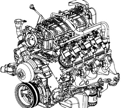
General view of the engine
Crankcase ventilation system The crankcase ventilation system is closed. Fresh air from the throttle body is supplied to the crankcase, where it mixes with crankcase gases and then through the crankcase ventilation valve enters the intake manifold. The consumption of crankcase gases depends on the vacuum in the intake manifold and is maintained at the required level by the ventilation system valve.
Attachment drive system
The system includes:
- drive belt and belt tensioner
- idler pulley
- crankshaft pulley
- brackets for mounted units
- mounted units:
- power steering pump (if driven by a belt) - generator
- air conditioning compressor (
- radiator fan (if driven by a belt)
- coolant pump
- vacuum pump
- air compressor.
The system may have 1 or 2 poly V-belts. Both sides of the belt may be used for the drive. The belt tension is maintained automatically by a spring tensioner. An idler pulley is installed to ensure the required angle of the belt wrapping the pulleys. Some systems use an idler pulley instead of an add-on unit that is not installed on the given vehicle model.
Camshaft
The steel camshaft is mounted on five plain bearings pressed into the engine block. The camshaft is driven from the crankshaft by a chain. On LC9/LY5/LMG engines, the shaft is driven directly, on LY6/L76/L92 engines - via a variable valve timing drive. The synchronizing ring of the camshaft position sensor is installed on the front side of the camshaft sprocket, the sensor itself is installed on the front cover of the engine. The camshaft is protected from axial movement by a lock.
Crankshaft
The crankshaft is cast from high-strength cast iron. The crankshaft is mounted on five main bearings. The crankshaft journals are undercut and rolled for strengthening. A thrust bearing is installed in the central main bearing. A synchronizing ring of the shaft position sensor is pressed onto the rear flange of the crankshaft. It is not serviced separately.
Cylinder head
The cylinder heads are cast from aluminum and carry pressed guide bushings and valve seats made by powder metallurgy. The front part of the heads has channels for releasing air from the cooling system. The valve covers are secured with 4 bolts.
Cylinder block
On LC9/L76/L92 engines the block is cast from aluminum, on LY5/LMG and LY6 engines - from cast iron. The block is made according to the V-shaped scheme with a 90-degree camber angle. The main bearing caps are fastened with four vertical and two tie bolts. Engine blocks with and without a cylinder deactivation system are different.
Exhaust manifolds
The exhaust manifolds are cast from cast iron. A heat shield is attached to each exhaust manifold.
Intake manifold
The intake manifold is common for both engine half-blocks. Brass inserts are screwed into the manifold to fasten the fuel manifold, throttle body and wire bundle support. The intake manifold is sealed on the half-blocks with a special disposable gasket. The intake manifold does not have a cooling jacket.
Oil pan
The oil pan is cast from aluminum. The oil pan carries the oil filter, the screen-damper and the oil level sensor. On early models, a channel was made in the pan for installing the bypass valve of the oil filter. Also in the pan, there is a pressure-reducing valve for the oil pressure of the fuel supply control system. It is very important to correctly install the pan at the junction of the rear part of the block and the automatic transmission housing.
Piston and connecting rod
The pistons are cast from aluminum and have two compression and one oil scraper ring. The piston head can be flat or with a displacer. The pin is installed in the piston and connecting rod with a gap. The pistons of all engine models have a graphite skirt coating. The piston and pin are replaced only as a pair.
Valve cover
The valve covers are cast from aluminum. The covers carry the ignition coils. The valve of the crankcase ventilation system is installed in the cover of the left half-block, the cover of the right half-block has an oil filler neck and an air supply channel for the crankcase ventilation system.
Valve drive
The valves are driven by hydraulic tappets, rods and rocker arms from the camshaft. There is no clearance in the valve drive. On some engine models, cylinders 1, 4, 6 and 7 can be switched off in some operating modes to improve fuel efficiency, (even cylinders are in the right half-block, odd cylinders are in the left half-block).
Cylinder deactivation system
General Motors' Active Fuel Management system can shut off four of the eight cylinders under light engine load to improve fuel economy, converting the engine from a V8 to a V4.
Oil manifold of hydraulic tappets of the cylinder deactivation system
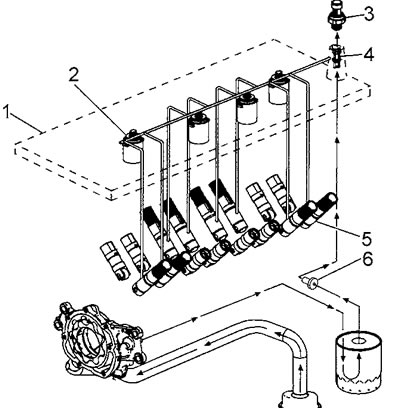
The oil manifold (1) of the hydraulic tappets is bolted to the top of the engine block under the intake manifold. Four normally closed electromagnetic valves (2) are installed in the manifold. Each electromagnetic valve directs engine oil to the tappets (5) of the intake and exhaust valves. The oil pressure in the system is regulated by a pressure reducing valve (6), which is installed in the oil pan.
Oil manifold of hydraulic tappets of the cylinder deactivation system
When the preconditions for cylinder shutdown arise, the electronic control unit begins to activate the electromagnetic valves in the order of cylinder operation. When the electromagnetic valves are activated, engine oil flows through eight vertical channels (two per cylinder) from the oil collector is fed into the tappet gallery in the engine block and the engine switches to the V4 configuration, see below. When operating conditions require a return to the V8 configuration, the ECM deactivates the solenoids and oil is dumped from the tappet cavity into the oil collector.
The oil manifold body has several channels for releasing air that has entered the system.
To prevent dirt from entering the hydraulic valve control system, a replaceable oil filter (4) is installed at the inlet to the oil manifold. An oil pressure sensor (3) is installed behind the filter, the signal from which is processed by the engine control unit.
Cylinder deactivation system tappets
Cylinder deactivation system tappets
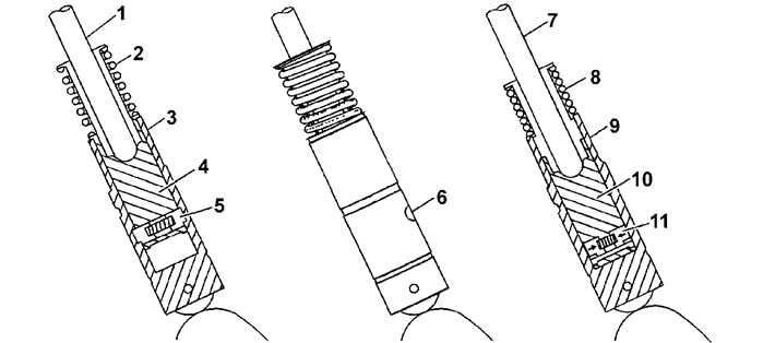
When the engine is running according to the V8 scheme, the operation of the tappets of the cylinder deactivation system is no different from the operation of conventional tappets. Here, the electromagnetic valves of the oil manifold are closed and the oil pressure is not transmitted to the tappet cavity. The rod (1) of the tappet moves up and down and drives the cylinder valves via the rocker arm. The locking pins (5), loaded by the force of the spring, protrude from the inner housing of the tappet and mechanically connect the inner housing of the tappet (4) with the outer housing (3).
When the engine control unit decides to deactivate the cylinders, the electromagnetic valves direct oil from the oil manifold to the input (6) of the tappet. The oil pressure overcomes the force of the spring of the locking fingers, pushing the fingers (11) into the housing and breaking the mechanical connection of both tappet housings. The engine switches to V4 operation. Now the rod (7) remains stationary, and the outer housing (9) moves up and down independently of the movement of the inner housing (10). Spring (8) maintains contact in the drive, eliminating valve train noise.
When the control unit switches the engine to V8 mode, the pressure at the tappet inlet is released, the locking finger spring restores the mechanical connection in the tappet.
Variable valve timing drive and electromagnetic valve
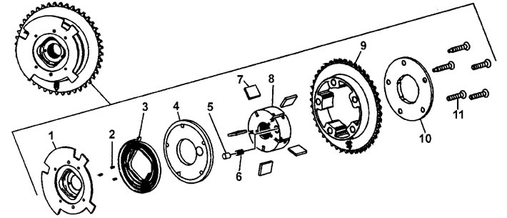
Variable valve timing drive. 1 - camshaft position sensor synchronizing ring, 2 - pin, 3 - return spring, 4 - front cover, 5 - retainer pin, 6 - retainer spring, 7 - blades, 8 - rotor, 9 - stator, 10 - rear cover, 11 - bolt
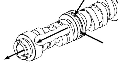
The camshaft of engines with variable valve timing has a channel for supplying oil to the drive.
Oil is supplied to the drive from the engine lubrication system from the journal of the 2nd bearing.
The electromagnetic valve of the phase change drive consists of a housing, a spool valve (1), a return spring (2), an oil filter (3), a check valve spring (4) and a check valve ball (5).
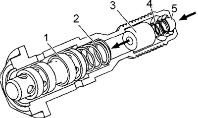
The position of the spool valve is determined by the system magnet and the engine control unit.
When the spool valve moves to a certain position, oil flows through the valve to the phase change actuator. The electromagnetic valve must be replaced each time it is removed. The actuator magnet (752) is located in the front engine cover and is sealed by a gasket (753).
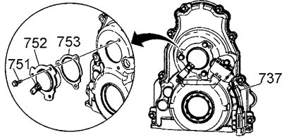
The actuator magnet is controlled by the engine control unit via a modulated 12-volt signal. When the magnet is activated, the spool valve of the actuator solenoid valve moves.
The phase change drive is a vane-type hydraulic motor that changes the angular position of the camshaft relative to the position of the crankshaft.
The lift and duration of the valve opening remain unchanged. The phase change drive is serviced only as an assembly.