
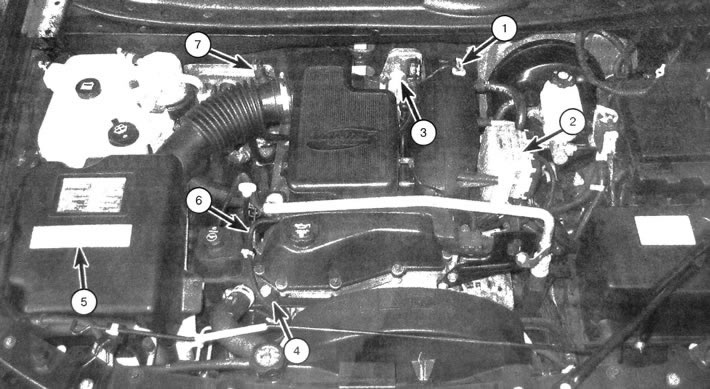
1.1. Location of engine management and exhaust gas toxicity control system components 1. Manifold Absolute Pressure (MAP) Sensor; 2. Control unit (PCM); 3. Throttle block; 4. Camshaft position sensor (CPS); 5. Vehicle Emission Control Information (VECI) Label; 6. Camshaft Phase Correction Device Solenoid Valve - Replacement; 7. Supply air temperature sensor
The use of an electronic engine control system reduces the content of unburned fuel-air mixture residues and fuel vapors in the exhaust. This design provides improved engine performance and increased fuel efficiency. The control system includes the following elements and subsystems:
- Electronic engine management system
- Crankcase ventilation system
- Exhaust gas recirculation system
- Fuel vapor recovery system
- Additional air injection system
- Catalytic converter
All of the listed subsystems, one way or another, relate to the general exhaust toxicity reduction system.
The subsections of this chapter include general information as well as descriptions of inspection and testing procedures that are within the competence of the amateur mechanic. Descriptions of procedures for replacing elements of all the above subsystems are also provided.
Before making an assumption about the failure of the exhaust toxicity reduction system components, it is necessary to exclude a malfunction of the ignition and fuel injection system components. Diagnostics of most engine systems and emission control require the use of specialized devices and equipment. Performing such procedures requires the mechanic to have the necessary experience. If the complexity of diagnostic and maintenance procedures is beyond the capabilities of the car enthusiast, contact a service and repair station with the appropriate level of qualification.
It should be noted that most Emission Control System problems are caused by damaged or loose vacuum hose connections or electrical connectors, so the inspection should begin with a thorough inspection of the hoses and wiring.
Although the engine management and emission control systems on newer vehicle models are extremely complex, most inspections and maintenance can be performed by the vehicle owner using common tools and equipment, as well as relatively inexpensive measuring instruments.
Note: Before affecting emission control system components, verify warranty coverage by obtaining reliable information from a source directly related to the manufacturer. After the warranty period has expired, in order to save money, you can independently perform the diagnostic and component replacement procedures described in this chapter.
Strictly follow the safety requirements given in this chapter. It should be noted that there may be a discrepancy between the arrangement of elements in the illustrations provided and on a specific vehicle, which is explained by the constant modification that the manufacturer carries out during the production of this model.
The Vehicle Emission Control Information (VECI) label is located in the engine compartment (see illustration). The vehicle used to create this manual had such a plate located on the underside of the hood. Sometimes it is located on the top crossbar of the radiator. The plate contains the adjustment parameters, as well as a diagram of the location of the vacuum hoses and other elements. Before servicing the engine management system or emissions control system, make sure the label is in place. If there is any discrepancy between the information provided on the label and in this manual, the information provided on the VECI label shall take precedence.
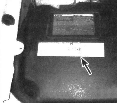
1.6. The Vehicle Emission Control Information (VECI) label, located in the engine compartment, provides information about the system components, vacuum hose routing, etc.