
Contents: Diagnostic equipment ↧ General description of the OBD system ↧ System sensors ↧ Drive units of the system ↧ Reading fault codes from the… ↧ Clearing fault codes from the… ↧ Decoding diagnostic codes ↧
Diagnostic equipment
1. To check the condition of the injection system elements and reduce exhaust toxicity, you need to use a digital multimeter (see illustration). The previously developed analog multimeter should be preferred to the new digital device for the following reasons. An analog multimeter does not record hundredths and thousandths of Volts, Amps and Ohms. Accuracy of measurements is especially important when checking electronic circuits, which are often under low voltage. Another factor that indicates the preference of a digital multimeter is the high resistance of its internal circuit. The digital device has an internal circuit with extremely high resistance (10000000 Ohm). Since the voltmeter is connected in parallel to the circuit being tested, it is very important that no voltage is applied to the parallel circuit that includes the voltmeter itself. When measuring high voltage circuits (9 - 12 V), voltage loss in the parallel circuit does not significantly affect the measurement results. In contrast, when diagnosing low voltage circuits, such as a circuit that includes an oxygen sensor, the loss may be comparable to the overall circuit voltage. There are some exceptional cases where testing some sensors requires the use of an analog instrument.
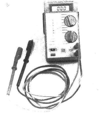
2.1 Digital multimeters can be used to test all types of circuits; these devices are more accurate than analog multimeters due to the high resistance of their internal circuits. which is important when measuring on low voltage circuits connected to the system processor
2. Portable scanners are the most effective and versatile devices for diagnosing engine management systems of cars of recent years of production (see illustration). Before starting diagnostics, make sure that the available scanner corresponds to the manufacturer, modification and year of production of the vehicle being diagnosed. It is often possible to purchase special cartridges for the scanner, with which you can diagnose cars of specific brands (FORD, GMC, CHRYSLER etc.). Some brands are classified according to the place of assembly (Asia. Europe, USA, etc.).
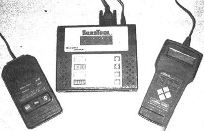
2.2. The Actron OBD-II, Actron Scantool and AutoXray XP240 scanners are powerful diagnostic equipment. These devices are equipped with diagnostic software, so they are able to display almost any information related to the engine management system
3. When working with the OBD-II diagnostic system, it is necessary to use a special scanner. Such scanners are developed and produced by several manufacturers. Before purchasing a scanner, get additional information from the store regarding the range of diagnostic scanners and their prices.
General description of the OBD system
4. All the described vehicles are equipped with the second generation OBD-II on-board diagnostics system. The system consists of an on-board computer (PCM), information sensors and drive units.
5. The RCM unit receives pulses from various sensors and other electronic devices (switches, relays, etc.). After processing the information received from the RCM, control signals are sent to various drive relays, solenoid valves and other devices (for example, fuel injectors). The PCM has a special setting that ensures optimization of fuel economy parameters, engine performance and exhaust toxicity levels.
6. Since the engine management system has a warranty that expires if the system components are damaged by independent action on them, you should not diagnose or replace the PCM at home until the warranty period has expired. If the warranty period has not expired, in case of system or PCM malfunctions, you should contact the authorized service station.
System sensors
7. The accelerator pedal position sensor (APP) is located on the accelerator pedal and consists of two separate switches enclosed in a single housing. This produces two separate pulses, one in the low voltage circuit and one in the 5 volt circuit. The voltage of the first switch increases as the accelerator pedal is depressed, while the voltage of the second switch decreases. The APP sensor, together with other information sensors, ensures the operation of the automatic throttle drive system.
8. The camshaft position sensor (CMP) transmits a signal to the PCM that determines the position of the camshaft. Based on the pulses from this sensor, as well as the crankshaft position sensor, the PCM synchronizes the fuel injection phases.
9. The crankshaft position sensor (CPS) transmits a signal to the control unit that determines the position of the crankshaft corresponding to the TDC of the first piston during each engine operating cycle. Based on the pulses received, the PCM unit controls the ignition phases and synchronizes the fuel injection phases.
10. The coolant temperature sensor (ECT) transmits a signal to the PCM, which determines the coolant temperature. The sensor signals are taken into account when determining the optimal fuel-air mixture ratio, as well as when calculating the ignition phases.
11. The intake air temperature (IAT) sensor is used to determine the temperature of the air entering the intake manifold. The sensor pulses are the initial ones when determining the injector opening duration in the PCM.
12. The knock sensor (KS) contains a piezoelectric element that emits pulses depending on the vibration of the cylinder block. The signals are used to determine the presence of engine detonation. When the corresponding sensor signals are received by the PCM, the ignition angle is reduced, thereby preventing detonation.
13. The manifold absolute pressure (MAP) sensor is used to determine the pressure in the intake manifold, as well as the external atmospheric pressure. Based on the signals received by the RCM, the engine load is determined, and in accordance with the change in load, the fuel-air mixture ratio is adjusted.
14. The Mass Air Flow (MAF) sensor is designed to determine the mass of air passing through the sensor housing and entering the engine. The sensor signals are processed in the PCM, where the amount of fuel required to form the optimal fuel-air mixture is determined.
15. The oxygen sensor (O2) produces signals that change depending on the oxygen content in the exhaust. Based on the sensor signals, the fuel-air mixture ratio is determined in the PCM. If necessary, the mixture is enriched or depleted.
16. The Throttle Position Sensor (TPS) detects the movement and determines the position of the throttle valve. The corresponding signal is transmitted to the PCM, on the basis of which the closed, normal or fully open position of the throttle block is determined. These data, together with signals from other sensors, determine the opening period of the injector valves and also serve as the basis for automatic adjustment of the ignition phases. It should be noted that in the vehicles described the sensor is integrated into the throttle unit. If necessary, the entire unit is replaced.
17. The vehicle speed sensor (VSS) transmits a signal to the PCM indicating the vehicle speed.
18. Other input signals from the electronic unit come to the PCM from various switches and electrical circuits, the state of which determines the operating mode of the vehicle. These pulses come from the following switches and electrical circuits.
- a) Air conditioning system
- b) Battery power circuit
- c) Brake light switch
- d) Cruise control system
- e) EGP valve position sensor
- f) Engine oil pressure and level sensor
- g) Fuel vapor recovery system
- h) Fuel level and pressure sensor in the fuel tank
- i) Ignition switch
- j) Park/Neutral selector position sensor (PNP)
- k) Sensor signal circuits and ground loops
- l) Gearbox switches
Drive units of the system
19. The air conditioner clutch relay provides control of the compressor clutch from the PCM electronic unit.
20. The camshaft phase adjustment system receives pulses from the PCM to the actuator solenoid valve, thereby adjusting the position of the camshaft cams to optimize engine performance.
21. Indicator "Service Engine Soon" is activated by the PCM unit when a malfunction occurs in the electronic engine management system.
22. The cruise control system is controlled by the PCM to ensure the operation of the cruise control system.
23. The engine cooling fan relay is used for electronic control of the fan from the PCM unit depending on the pulses from the coolant temperature sensor.
24. The EVAP canister purge and vent valve solenoids are controlled by the PCM to purge the canister and direct fuel vapor from it into the intake manifold for combustion in the engine chambers.
25. The fuel injectors are opened by the PCM in a separate order in accordance with the ignition sequence. The electronic unit also controls the open time of the injector (pulse width). This value (measured in milliseconds) determines the amount of fuel supplied. A detailed description of the fuel supply system, as well as the operating principle and procedure for replacing injectors, is given in Chapter 4.
26. The fuel pump relay is activated by the PCM when the ignition key is turned to the Start or Run position. When the ignition switch is closed, the relay is activated and primary fuel pressure is created in the system. Chapter 4 provides procedures for checking the operation and replacing the fuel pump.
27. The idle air control valve (IAC) is designed to regulate the flow of air that bypasses the throttle body when it is fully closed or in the idle position. The valve receives signals from the PCM. When the engine is under additional load (for example, low-speed maneuvering, operation of the air conditioning system, etc.) idle speed may drop, to the point of engine stalling. To prevent this situation, an additional amount of air is supplied through the valve, which allows the engine speed to be maintained at the level required to overcome the load.
28. The ignition coils/ignition unit are controlled by the PCM, which is carried out depending on the operating modes of the engine. Chapter 5 provides more detailed information on ignition coils and the igniter unit.
Reading fault codes from the electronic memory of the microprocessor
Note: To obtain fault codes from the PCM microprocessor memory, a special scanner must be used. If you do not have the required diagnostic device, please bring your vehicle to a branded station.
29. If the PCM registers a malfunction in the emission control system, as well as in its individual components and electrical circuits, the SERVICE ENGINE SOON indicator, sometimes called the malfunction indicator lamp (MIL), comes on in the instrument cluster. The indicator will remain on until the malfunction is corrected and the code is cleared from the PCM electronic memory, or until the malfunction is not registered for several driving cycles.
30. To obtain codes from the PCM memory, it is necessary to use a special scanner. Connect a scanner with an OBD-II interface to the vehicle's diagnostic port (see illustration). The use of this equipment allows you to determine the root causes of engine malfunctions. The scanner also has a function for freezing the basic parameters of the corresponding sensors and drive devices at the moment of a malfunction in the engine management systems or a reduction in exhaust toxicity. The parameters registered at the time the fault code was recorded are stored in the memory. The presence of this function allows you to examine circuits and evaluate their parameters when diagnosing faults that are intermittent in nature. If the malfunction is of an intermittent nature and a diagnostic scanner is not available, take the vehicle to a company station for testing.
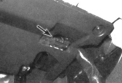
2.30. As a rule, the diagnostic connector is located under the instrument panel
Clearing fault codes from the electronic memory of the microprocessor
31. After determining the cause of the malfunction, repair or replace the failed components and clear the electronic memory of the PCM. It is preferable to delete codes from the memory using a scanner, but this can also be done by disconnecting the battery from the electronic power supply for at least 30 seconds. You can disconnect the power by removing the PCM fuse, disconnecting the PCM power circuit connector located next to the positive battery terminal (if the presence of a connector is provided for by the design), and also disconnecting the negative cable from the battery. After installing new electronic components of the toxicity reduction system, before starting the engine, it is necessary to clear the electronic memory of the microprocessor from fault codes. The operating parameters of each sensor are stored in the PCM memory. If a new sensor is put into operation before the parameters of the old sensor are cleared, a fault code may be registered in the PCM.
Decoding diagnostic codes
32. The table below provides a breakdown of the codes that a car mechanic can obtain when performing the procedures independently. When diagnosing at a branded center, using special equipment and software, significantly more diagnostic codes can be obtained. Not all codes apply to a specific model of the described series. Registration of a fault code is not always accompanied by the SERVICE ENGINE SOON indicator. To obtain fault codes on all models, it is necessary to use a diagnostic scanner.
| Code | Probable cause |
| P0013 | Malfunction in the electrical circuit of the camshaft phase adjustment device |
| P0014 | Camshaft Phase Period Failure |
| P0105 | Voltage in the MAP sensor circuit is outside the set limit |
| P0107 | Absolute Pressure (MAP) Sensor Circuit Low Input |
| P0108 | Absolute Pressure (MAP) Sensor Circuit High Input |
| P0112 | IAT Sensor Circuit Input Low |
| P0113 | IAT Sensor Circuit Input Extremely High |
| P0117 | Weak input signal from ECT sensor circuit |
| P0118 | ECT sensor circuit input signal too high |
| P0122 | Weak input signal from the TP sensor circuit |
| P0123 | TP sensor circuit input signal too high |
| P0125 | Coolant temperature is too low to activate the fuel system feedback circuit |
| P0128 | Ambient temperature too low (ECT) |
| P0130 | Oxygen Sensor Circuit Signal and Performance Not Within Normal Range |
| P0131 | Weak signal in the oxygen sensor circuit (top sensor, left row) |
| P0132 | Oxygen sensor circuit signal too high (top sensor, left row) |
| P0133 | Oxygen sensor circuit feedback delay (top sensor, left row) |
| P0134 | No activity in oxygen sensor circuit (top sensor, left row) |
| P0135 | Oxygen sensor heating element circuit fault (top sensor, left row) |
| P0137 | Weak signal in the oxygen sensor circuit (lower sensor, left row) |
| P0138 | Oxygen sensor circuit signal too high (lower sensor, left row) |
| P0140 | No activity in oxygen sensor circuit (lower sensor, left row) |
| P0141 | Oxygen sensor heating element circuit fault (lower sensor, left row) |
| P0171 | Lean fuel/air mixture, left lane |
| P0172 | Enrichment of the air/fuel mixture, left row |
| P0175 | Enrichment of the air/fuel mixture, right row |
| P0201 -P0206 | Malfunction in the control circuit of the injector of one of the cylinders |
| P0300 | Misfires |
| P0301-P0306 | Misfires in a specific cylinder |
| P0326 | Malfunction in the diagnostic circuit of the knock sensor |
| P0327 | Knock Sensor Circuit Low Output (front Knock Sensor) |
| P0332 | Knock Sensor Circuit Low Output (rear knock sensor) |
| P0335 | Crankshaft Position Sensor Circuit Malfunction |
| P0336 | Non-compliance with the standard value or characteristics of the crankshaft position sensor signal |
| P0340 | Camshaft Position Sensor Circuit Malfunction |
| P0341 | Camshaft position sensor signal value or characteristics not in compliance with the norm |
| P0420 | Reduced efficiency of catalytic converter system, left lane |
| P0440 | Malfunction of the fuel vapor recovery system |
| P0442 | Minor EVAP system leak |
| P0446 | EVAP Vent Valve Circuit Signal Value or Parameter Abnormal |
| P0449 | EVAP Vent Valve Control Circuit Malfunction |
| P0452 | EVAP Pressure Sensor Circuit Low Input |
| P0453 | EVAP Pressure Sensor Circuit Input Too High |
| P0480 | Cooling Fan Relay Control Circuit Malfunction |
| P0483 | Error in determining the speed of the cooling system fan |
| P0493 | Error in determining the speed of the cooling system fan |
| P0495 | Overestimation of required cooling system fan speed |
| P0502 | Vehicle Speed Sensor Circuit Low Input |
| P0503 | Intermittent failure in vehicle speed sensor circuit |
| P0506 | IAC sensor failure resulting in low idle speed |
| P0507 | IAC sensor failure causing high idle speed |
| P0526 | Loss of signal determining cooling fan speed |
| P0562 | Low system voltage |
| P0563 | High system voltage |
| P0601 | An error has been detected in the electronic memory of the RCM |
| P0602 | An error has been detected in the RSM program |
| P0603 | An error is detected when resetting the electronic memory of the RCM |
| P0604 | A random access memory (RAM) error was detected in the RCM |
| P0605 | An error was detected in the PCM storage device (ROM) |
| P0621 | Malfunction of the circuit connected to the generator L terminal |
| P0622 | Malfunction of the circuit connected to the generator terminal F |
| P0705 | Park/Neutral selector position sensor circuit fault |
| P0711 | Transmission Oil Temperature Sensor Circuit Signal Characteristics Out of Range |
| P0712 | Low Input in Transmission Oil Temperature Sensor Circuit |
| P0713 | Transmission Oil Temperature Sensor Circuit High Input |
| P0719 | Torque Converter Clutch Brake Switch Circuit Low |
| P0724 | Torque Converter Clutch Brake Switch Circuit High |
| P0740 | The torque converter clutch solenoid valve is not controlled via the circuit |
| P0741 | Torque converter stuck in the off position |
| P0742 | Torque converter stuck in the engaged position |
| P0748 | Malfunction in the pressure control valve circuit |
| P0751 | Non-compliance with the standard characteristics of the signals of the circuit of the solenoid valve for switching from 1 to 2 gear |
| P0753 | Malfunction in the 1st to 2nd gear shift solenoid valve circuit |
| P0756 | Non-compliance with the standard characteristics of the signals of the circuit of the solenoid valve for switching from 2 to 3 gear |
| P0758 | Malfunction in the 2nd to 3rd gear shift solenoid valve circuit |
| P0785 | Malfunction in the 2nd to 3rd gear shift solenoid valve circuit |
| R1120 | Throttle Position Sensor 1 Circuit Low Voltage |
| R1133 | Poor oxygen sensor switching (upstream oxygen sensor) |
| R1134 | Violation of the time phases of the oxygen sensor operation (upstream oxygen sensor) |
| R1137 | Low Voltage in Oxygen Sensor Circuit (downstream oxygen sensor) |
| R1138 | High Voltage in Oxygen Sensor Circuit (downstream oxygen sensor) |
| R1171 | During acceleration, the fuel-air mixture becomes leaner |
| R1220 | Throttle Position Sensor Signal Characteristics Out of Standard |
| R1221 | Mismatch between two throttle position sensors |
| R1258 | Enabling engine overheating protection mode |
| R1271 | Excessive voltage difference between accelerator pedal position (APP) sensors 1 and 2 |
| R1275 | Accelerator pedal position sensor circuit voltage too high or too low |
| R1280 | Mismatch between two accelerator pedal position sensors 1 and 2 |
| R1336 | Crankshaft position sensor modes are not memorized |
| R1345 | Crankshaft/Camshaft Position Sensor Correlation |
| R1380 | Error in determining uneven road surface in the electronic unit of the brake system |
| R1381 | No serial data is received from the electronic brake system unit |
| R1441 | The fuel vapor recovery system is ventilated without purging |
| R1481 | Loss of signal determining cooling fan speed |
| R1482 | Voltage abnormality in cooling fan clutch circuit |
| R1484 | Error in determining cooling fan speed |
| R1512 | An impending or past error in determining the throttle position |
| R1514 | Air flow meter (MAF), air flow intensity differs from the calculated value |
| R1515 | Throttle Position Sensor (TPS), difference between actual and detected throttle position |
| R1516 | Throttle Position Sensor (TPS) Signal Characteristics Out of Range |
| R1621 | Non-compliance with the standard characteristics of the parameters of the electronic memory of the RCM |
| R1630 | Malfunction in the anti-theft alarm system controller (timeout in password entry mode) |
| R1631 | Entering the wrong password for the anti-theft alarm system |
| R1633 | No voltage when ignition switch position is 0, and voltage is present when ignition switch position is 1 |
| R1635 | Circuit with voltage of 5 volts |
| R1637 | Malfunction in the circuit connected to the generator L terminal |
| R1638 | Failures in the electromagnetic cycle of the generator |
| R1639 | Circuit with voltage of 5 volts |
| R1682 | Voltage at ignition switch position 1 is less than 10 volts |
| R1810 | Gearbox oil pressure sensor malfunction |
| R1860 | Malfunction in the solenoid valve circuit of the torque converter clutch pulse width change device |
| R1870 | Gearbox slippage |