


P0100. Mass Air Flow Sensor Circuit Malfunction.
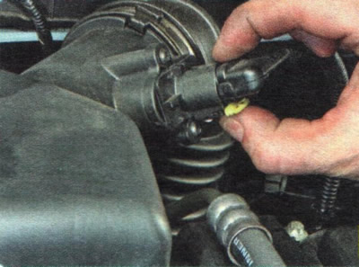
1. Check the reliability of the wiring harness connector to the combined mass air flow and intake air temperature sensor connector.
2. If the cause of the malfunction is not in the shoe fastening, check the electrical circuits of the sensor (see "Diagnostics of faults of on-board electrical equipment"), and if necessary, replace the sensor (see "Removal and installation of engine management system sensors").
P0101. Mass fuel flow sensor signal out of acceptable range.
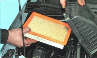
1. Check the condition of the air filter element (see "Replacing the air filter element")...
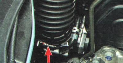
2. ...reliability of tightening of air supply hose clamps...
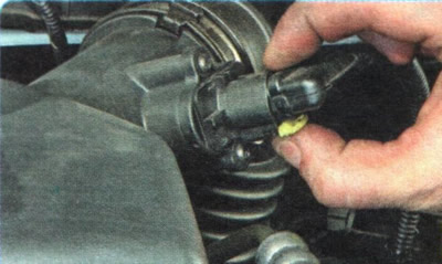
3. ...and the reliability of the fastening of the wiring harness block to the connector of the combined mass air flow and intake air temperature sensor.
4. If the filter element of the air filter is clean and the duct and wiring harness of the combined mass flow and incoming air temperature sensor are securely attached, check the sensor's electrical circuits (see "Diagnostics of faults of on-board electrical equipment"), and if necessary, replace the sensor (see "Removal and installation of engine management system sensors").
P0105. Absolute pressure sensor malfunction (rarefaction) in the intake pipe.
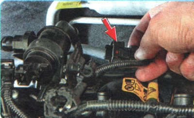
1. Check the reliability of the wiring harness connector to the absolute pressure sensor connector (rarefaction) in the intake pipe.
2. If the cause of the malfunction is not in the shoe fastening, check the electrical circuits of the sensor (see "Diagnostics of faults of on-board electrical equipment"), and if necessary, replace the sensor (see "Removal and installation of engine management system sensors").
P0110. Intake air temperature sensor malfunction.
The troubleshooting procedure is the same as for code P0100.
P0111. Inlet air temperature sensor signal is out of acceptable range.
The troubleshooting procedure is the same as for code P0101.
P0116. Coolant temperature sensor signal out of acceptable range.
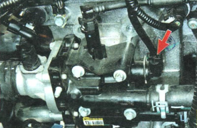
1. Check the reliability of the wiring harness connector fastening to the coolant temperature sensor connector.
2. If the cause of the malfunction is not in the shoe fastening, check the electrical circuits of the sensor (see "Diagnostics of faults of on-board electrical equipment"), and if necessary, replace the sensor (see "Removal and installation of engine management system sensors").
P0117. Coolant Temperature Sensor Low Input Voltage.
The troubleshooting procedure is the same as for code P0116.
P0118 Coolant Temperature Sensor High Input Voltage.
The troubleshooting procedure is the same as for code P0116.
P0135. Oxygen Sensor Control Heater Circuit Malfunction.
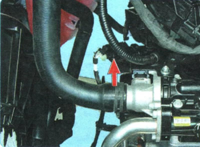
1. Check the reliability of the connection of the parts of the wiring harness block of the control oxygen concentration sensor.
2. If the cause of the malfunction is not in the connection of the parts of the block, check the electrical circuits of the sensor (see "Diagnostics of faults of on-board electrical equipment"), and if necessary, replace the sensor (see "Removal and installation of engine management system sensors").
P0141. Oxygen Sensor Heater Circuit Malfunction.
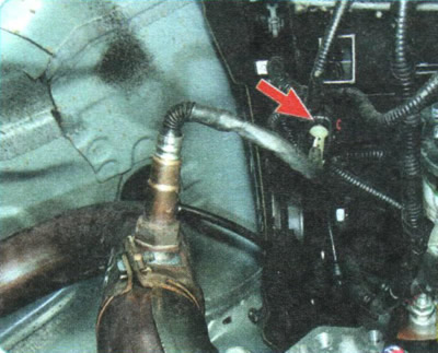
1. Place the vehicle on a lift or inspection pit, remove the engine crankcase guard (see "Removal and installation mudguards and engine crankcase protection") and check the reliability of the connection of the parts of the diagnostic oxygen concentration sensor wiring harness block.
2. If the cause of the malfunction is not in the connection of the parts of the block, check the electrical circuits of the sensor (see "Diagnostics of faults of on-board electrical equipment"), and if necessary, replace the sensor (see "Removal and installation of engine management system sensors").
P0201, P0202, P0203, P0204. Malfunction of the injector circuit of the 1st, 2nd, 3rd or 4th cylinder, respectively.
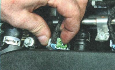
1. Check the reliability of the wiring harness connector fastening to the connector of the corresponding injector. To access the injector connectors, remove the engine wiring harness holders by performing operations 1-27 of subsection "Removal and installation the fuel rail".
2. If the cause of the malfunction is not in the shoe fastening, check the electrical circuit of the injector (see "Diagnostics of faults of on-board electrical equipment"), and if necessary, replace the injector (see "Removal, inspection and installation of injectors").
P0230. Fuel pump primary control circuit malfunction.
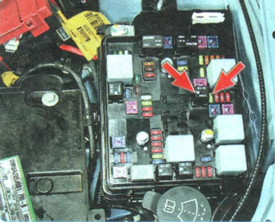
1. Check the integrity of fuse No.35 and the reliability of the fastening of fuel pump relay No.34 in the engine compartment mounting block.
2. If the fuse is good and the relay is securely fastened, check the electrical supply circuit to the fuel pump relay (see "Diagnostics of faults of on-board electrical equipment").
P0300. Misfire in one or more cylinders.
The troubleshooting procedure is described below for codes P0301-P0304.
P0301, P0302, P0303, P0304. Misfires in cylinders 1, 2, 3 or 4, respectively.
If the above codes are combined with fault codes of any engine management system components, then the misfires in the cylinders are caused by the failure of these components. In this case, the fault should be looked for using the methods described above for the corresponding fault codes.
If misfires are observed in only one cylinder, the fault should be looked for in the following order.
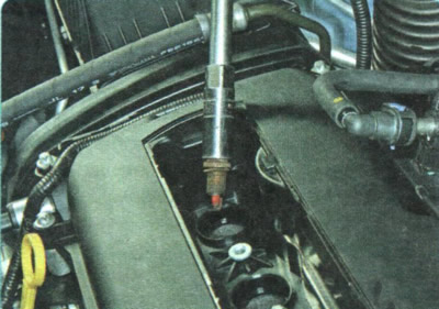
1. Remove the spark plug from the cylinder that is misfiring (see "Replacement and maintenance of spark plugs"). Inspect the candle and compare its appearance with the photographs provided in the subsection "Diagnosing engine condition by the appearance of spark plugs". If the candle is black and wet, it can be thrown away.
2. If the spark plug appears to be in good condition, try replacing it with a new one or swapping the spark plugs.
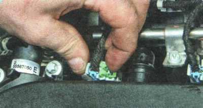
3. If misfires in the cylinder persist after replacing the spark plug, check the reliability of the wiring harness connector to the connector of the corresponding injector. To access the injector connectors, remove the engine wiring harness holders by performing operations 1-27 of subsection "Removal and installation the fuel rail".
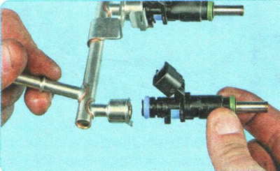
4. If the injector connector is connected securely and misfires persist, try swapping the injectors (see "Removal, inspection and installation of injectors").
5. If misfires continue in the same cylinder after reversing the injectors, check the electrical circuit of the injector for that cylinder (see "Diagnostics of faults of on-board electrical equipment").
6. If, as a result of the measures taken, misfires in the cylinder do not disappear, check the compression in the cylinder (see "Checking the compression in the cylinders"). Normal compression is more than 1.0 MPa, a decrease in compression indicates the need for engine repair.
7. If all checks have failed, the cause may be a faulty ignition coil unit or air being sucked into the cylinder through the intake manifold gasket.
If misfires are observed in all cylinders, the fault should be looked for in the following order.
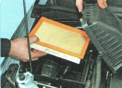
1. Check the condition of the air filter element (see "Replacing the air filter element")...
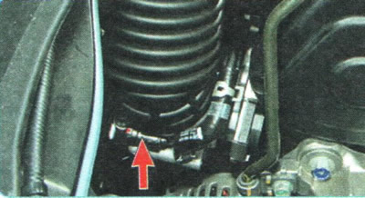
2. ...and the reliability of tightening the clamps of the air supply hose.
3. Check the fuel pressure in the fuel system (see "Checking the pressure in the fuel system"). If the pressure is below normal, replace the fuel module (see "Removal and installation the fuel module").
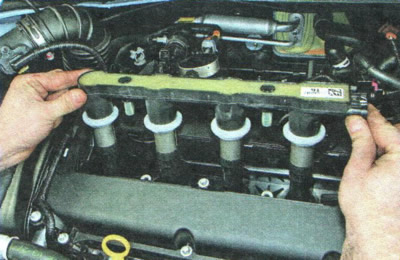
4. If the fault is not corrected, remove the ignition coil assembly (see "Removal and installation the ignition coil unit"). Check the coil block for burnouts and cracks.
5. If the misfires do not disappear as a result of the measures taken, check the compression in the cylinders (see "Checking the compression in the cylinders"). Normal compression is more than 1.0 MPa, a decrease in compression indicates the need for engine repair.
6. If all checks have failed, the cause may be a faulty ignition coil unit or air being sucked into the cylinders through the throttle assembly and intake manifold gaskets.
P0325 Knock Sensor Circuit Malfunction.
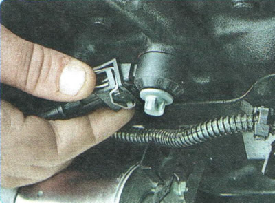
1. Place the vehicle on a lift or inspection pit, remove the engine crankcase guard (see "Removal and installation mudguards and engine crankcase protection") and check the reliability of the wiring harness connector to the knock sensor connector.
2. If the cause of the malfunction is not in the shoe fastening, check the electrical circuits of the sensor (see "Diagnostics of faults of on-board electrical equipment"), and if necessary, replace the sensor (see "Removal and installation of engine management system sensors").
P0335. Crankshaft Position Sensor Malfunction (when such a malfunction occurs, the engine usually stops).
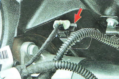
1. Check the reliability of the connection of the parts of the crankshaft position sensor wiring harness connector (the shoe is located at the rear of the engine cylinder block, behind the starter).
2. If the cause of the malfunction is not in the shoe fastening, check the electrical circuits of the sensor (see "Diagnostics of faults of on-board electrical equipment").
3. If the fault is not corrected, check the reliability of the crankshaft position sensor fastening to the rear crankshaft oil seal (to do this you will have to remove the gearbox and flywheel), and if necessary, replace the sensor (see "Removal and installation of engine management system sensors").
P0340. Intake camshaft position sensor malfunction.
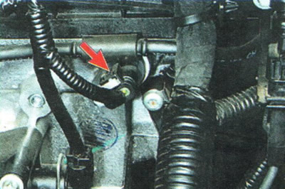
1. Check the reliability of the wiring harness connector to the intake camshaft position sensor connector and the reliability of the sensor to the cylinder head.
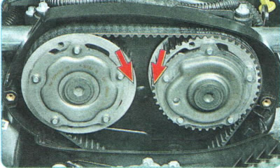
2. If the cause of the malfunction is not in the shoe fastening, set the piston of the 1st engine cylinder to the TDC position of the compression stroke (see "Setting the piston of the first cylinder to the TDC position of the compression stroke") and check the alignment of the marks on the variable valve timing mechanisms of the intake and exhaust camshafts. If necessary, rearrange the timing belt, aligning the marks (see "Replacing the timing belt").
3. If the marks on the variable valve timing mechanisms match, check the electrical circuits of the intake camshaft position sensor (see "Diagnostics of faults of on-board electrical equipment"), and if necessary, replace the sensor (see "Removal and installation of engine management system sensors").
P0365. Exhaust camshaft position sensor malfunction.
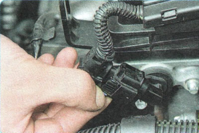
1. Check the reliability of the wiring harness connector to the exhaust camshaft position sensor connector and the reliability of the sensor to the cylinder head.
2. If the cause of the malfunction is not in the shoe fastening, set the piston of the 1st engine cylinder to the TDC position of the compression stroke (see "Setting the piston of the first cylinder to the TDC position of the compression stroke") and check the alignment of the marks on the variable valve timing mechanisms of the intake and exhaust camshafts. If necessary, rearrange the timing belt, aligning the marks (see "Replacing the timing belt").
3. If the marks on the variable valve timing mechanisms match, check the electrical circuits of the exhaust camshaft position sensor (see "Diagnostics of faults of on-board electrical equipment"), and if necessary, replace the sensor (see "Removal and installation of engine management system sensors").
P0420. Catalytic Converter Low Efficiency.
Most often, this fault code appears as a result of chemical poisoning of the active substance of the catalytic converter (in a Chevrolet Aveo, the neutralizer is part of the catalytic converter) combustion products of low-quality fuel, as well as melting of the core of the neutralizer due to afterburning of fuel in the exhaust manifold of the engine. Therefore, the first thing to do when the code P0420 appears is to change the place of refueling. Perhaps the neutralizer can still be saved. If after a run of about 500 km after changing the gas station, the engine management system malfunction indicator lamp continues to light, do the following.
1. Check for a breakthrough of exhaust gases through the joint of the catalytic converter and the cylinder head; if necessary, replace the catalytic converter gasket (see "Removal and installation the catalytic converter, replacing its gasket").
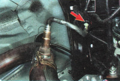
2. Place the vehicle on a lift or inspection pit, remove the engine crankcase protection (see "Removal and installation mudguards and engine crankcase protection") and check the reliability of the connection of the parts of the diagnostic oxygen concentration sensor wiring harness block.
3. If the cause of the malfunction is not in the connection of the parts of the shoe, check the electrical circuits of the sensor, see. "Diagnostics of faults of on-board electrical equipment", and if necessary, replace the sensor (see "Removal and installation of engine management system sensors").
If the checks do not reveal any faults, then the catalytic converter is faulty. In this case, replace the catalytic converter with a new one (see "Removal and installation the catalytic converter, replacing its gasket").