


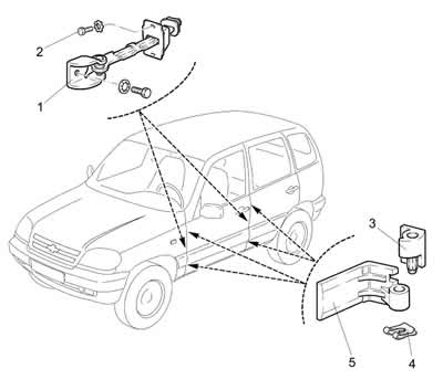
Figure 8-39. Removing the doors:
1 - door opening limiter;
2 - bolt;
3 - left movable loop;
4 - locking bracket;
5 - fixed loop.
Squeeze the tabs of the lock and remove button 4 (see figure 8-43) disabling the door lock.
Remove three key switches on the left door and one on the right, disconnect the connector blocks, remove the plugs 5 (figure 8-41), unscrew screws 3 and 4 securing handle 10 of door armrest 12, remove the armrest handle and side mirror trim.
Loosen the screw securing the trim 1, slide it back and remove the trim of the inner door opening handle 2.
Remove three self-tapping screws 6 (see figure 8-40) and remove pocket 9 of the front door trim.
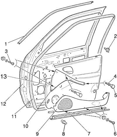
Figure 8-40. Removing the front door trim:
1 - upper seal of the front door opening;
2 - button;
3 - screw;
4 - screw;
5 - plug;
6 - screw;
7 - threshold seal;
8 - piston;
9 - door trim pocket;
10 - armrest handle;
11 - door opening seal;
12 - front door;
13 - front door trim.
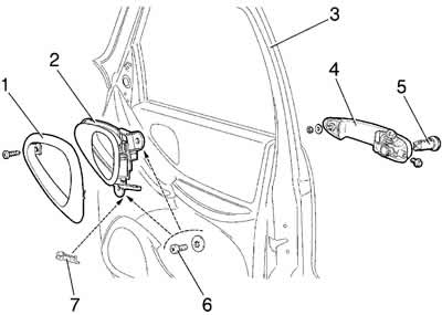
Figure 8-41. Removing the front door handles:
1 - inner door handle trim;
2 - inner door handle;
3 - front door;
4 - Front door outer handle;
5 - lock cylinder;
6 - screw;
7 - bracket.
Unscrew the two screws, press button 2 with a screwdriver and remove trim 13.
Disconnect the plug connectors of the outside mirror motor and front door wire harnesses.
Remove three screws 12 (see figure 8-52) and remove the outside mirror.
Remove the outer lower and upper seals of the drop glass.
Temporarily install the key switches, connect the negative terminal to the battery, and raise the sliding glass.
Remove the key switches and disconnect the negative terminal from the battery.
Loosen the bolt and remove the guide 1 (figure 8-42) lowering glass assembly with seal 2.
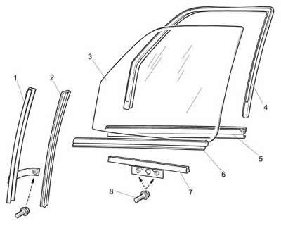
Figure 8-42. Removing the front drop-down glass:
1 - front right guide;
2 - lower seal;
3 - drop glass;
4 - upper seal;
5 - internal seal;
6 - outer seal;
7 - lowering glass holder;
8 - bolt.
Through the openings in the inner door panel, unscrew the two bolts 8 securing the clip 7 of the lowering glass 3 to the window lifter and remove the glass from the door cavity.
Disconnect connector 10 (figure 8-44) wiring harness of the 9 window lifter motor from the side door wiring harness connector.
Unscrew the four nuts 5 securing the window lifter and remove it together with the gear motor through the opening in the inner door panel.
Remove two screws 6 (see figure 8-41) fastenings of the inner handle 2 of the door lock drive, disconnect the rod 1 (see figure 8-43) and remove the handle.
Disconnect rods 5 and 7 of the outer handle from lock 9.
Unscrew the nut and bolt and remove the handle 4 (see figure 8-41) complete with rods 5 and 7 (see figure 814).
Unscrew the three screws and remove the lock 9 (see figure 8-43) complete with rods 1 and 2.
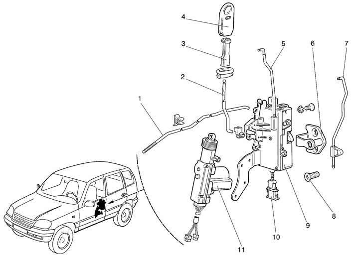
Figure 8-43. Front door locking mechanism:
1 - internal lock drive rod;
2 - button pull;
3 - Insert button;
4 - door lock release button;
5 - outer handle rod;
6 - lock retainer;
7 - lock release rod;
8 - retainer mounting screw;
9 - front door lock;
10 - gearmotor electrical connector;
11 - gear motor.
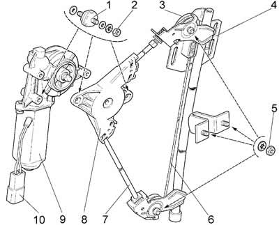
Figure 8-44. Front door window regulator:
1 - support;
2 - nut;
3 - roller;
4 - mounting plate for the drop glass;
5 - nut;
6 - cable;
7 - cable sheath;
8 - window lift mechanism;
9 - window lifter motor;
10 - gearmotor electrical connector.
Unscrew the three bolts securing the door opening limiter and remove it.
Remove the wiring harness from the door cavity.