


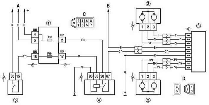
Figure 7-42. Control diagram of the external mirror gear motors:
1 - mounting block;
2 - motor reducers of external mirrors;
3 - control unit for external mirrors;
4 - front seat heating relay;
5 - ignition switch;
A - to power sources;
B - to the outdoor lighting switch;
C - diagram of conventional numbering of plugs in the block of the control unit of external mirrors;
D - diagram of conventional numbering of plugs in the outside mirror sockets.
The position of the outside mirrors can only be controlled when the ignition is on, since voltage is supplied to control unit 3 via relay 4, which is triggered when the ignition is turned on.
If the position of the outside mirrors is not adjusted, then it is necessary to check fuse F5 and relay 4, wires and their connections, control unit and gear motors. Replace faulty control unit and gear motors with new ones.