


The design of the gear motor allows it to be disassembled to eliminate minor faults (collector cleaning, etc.).
The rear window wiper connection diagram is shown in Figure 7-40. The rear window wiper and washer operation is controlled by switch 3 (lever position see figure 7-34).
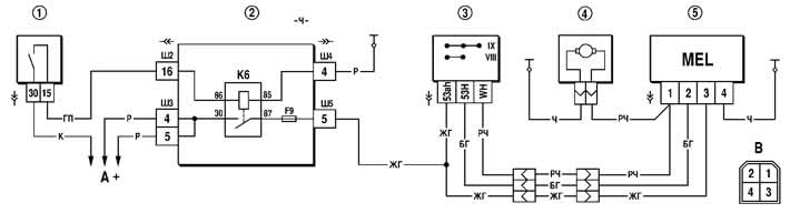
Figure 7-40. Rear window wiper and washer circuit diagram:
1 - ignition switch;
2 - mounting block;
3 - Rear window wiper and washer switch;
4 - rear window washer motor;
5 - rear window wiper motor;
A - to power sources;
B - the order of conventional numbering of the plugs in the block of the wiper motor;
K6 - additional relay.
For the rear window wiper, with a gear motor load of 1 Nm, a supply voltage of 13.5 V and an ambient temperature of (25±10)°C, the number of double strokes of the gear motor shaft in intermittent mode should be 16...18 min⁻¹, in continuous mode 20...30 min⁻¹, and the current consumption should not exceed 3 A.
(The article is based on data from the website CHEVYMAN)