
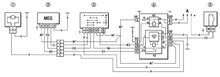
Figure 7-39. Windshield wiper and washer circuit diagram:
1 - windshield washer motor;
2 - Windshield wiper motor;
3 - Windshield wiper and washer switch;
4 - mounting block;
5 - ignition switch;
A - to power sources;
K2 - windshield wiper relay;
K6 - additional relay.
I mode - intermittent, carried out in positions II and III of the switch lever 3. This mode is provided by the electronic relay K2 type 524.3747 or 523.3747, installed in the mounting block. This relay also includes the wiper gear motor (low speed) when the windshield washer is turned on.
Mode II - constant, with low brush movement speed, is carried out in position IV of the switch lever 3. In this case, the supply voltage is supplied to the electric motor brush, which is in geometric neutral.
III mode - constant, with high brush speed. It occurs in position V of the switch lever 3. In this case, the supply voltage is supplied to the brush, shifted from the geometric neutral.
[The source of the article is available on the website: CHEVYMAN.ru]