


The switches are secured in the connector with latches. To replace a damaged switch (right or left) remove the steering gear shaft cover, squeeze the switch latches and remove it from the connector.
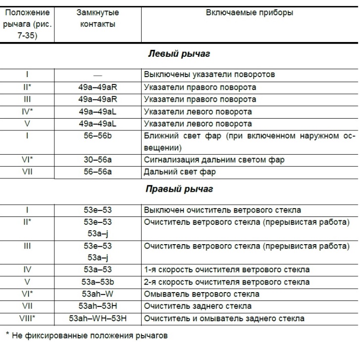
The positions of the switch levers are shown in Figure 7-36, and the contacts closed in this case are given in Table 7-6.
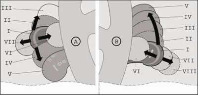
Figure 7-36. Positions of the steering column switch levers.
The initial positions are shown in bold lines, the fixed positions in thin lines, and the non-fixed positions in dotted lines.
Closing contacts at different positions of the steering column switch levers
(The material was created based on information from the website CHEVYMAN)