
Adjustment of the headlight beams should be carried out only by qualified personnel at a service station. Adjustment of the headlights is carried out using optical instruments. If there are none, then adjustment is allowed to be carried out using a screen (figure 7-26).
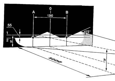
Figure 7-26. Headlight adjustment diagram:
1 - horizontal line corresponding to the centers of the headlights;
2 - a line passing through the centers of light spots;
A and B are vertical lines corresponding to the centers of the headlights;
O - center line;
h - distance of headlight centers from the floor.
The headlights are adjusted by turning screws 2 and 5 (see figure 7-27), which rotate the optical element in the vertical and horizontal planes.
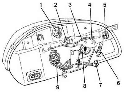
Figure 7-27. Headlight unit adjustment screws:
1 - direction indicator lamp socket;
2 - screw for adjusting the beam of light of the headlight in the horizontal direction;
3 - holder;
4 - lid;
5 - screw for adjusting the light beam of the headlight in the vertical direction;
6 - low beam lamp (or distant) sveta;
7 - low beam lamp socket (or distant) sveta;
8 - latch;
9 - low beam lamp socket (or distant) sveta.
Place a fully fueled and equipped vehicle, with a load of 735 N (75 kgf) on the driver's seat, on a level horizontal surface 5 m from the screen (plywood shield measuring about 2x1 m, etc.) so that the car's axis is perpendicular to it. Before marking the screen, make sure that the air pressure is 0.19 MPa (1.9 kgf/cm²), and then rock the car from side to side to settle the suspension springs.
Draw vertical lines on the screen: axial 0 and lines A, B, C and E passing through the points corresponding to the centers of the headlights. These lines should be symmetrical relative to the axial line of the car. At a height h corresponding to the distance of the centers of the headlights from the floor, draw line 1 and below it 55 mm line 2 of the centers of the light spots.
Set the headlight range control on the instrument panel to the position corresponding to the load of the vehicle with one driver.
Turn on the low beam. Sequentially, first for the right headlight (the left one is covered by something or disconnected from the wiring harness), and then for the left (the right one is closed) adjust with screws 2 and 5 (see figure 7-27) headlight beams. In this case, the displacement of the headlight beam should not exceed ±3° in the vertical plane and ±2° in the horizontal plane.
For correctly adjusted headlights, the upper border of the light spots should coincide with line 2 (see figure 7-26), and the points of intersection of the horizontal and inclined sections of the light spots with lines A and B.
[The original article can be found on the resource «ChevyMan.ru»]