


The ignition switch is checked for correct contact closure in different key positions (Table 7-3), operation of the anti-theft device and the presence of communication with the vehicle anti-theft system. Voltage from the battery and generator is supplied to contact "30" (figure 7-3). To relieve the ignition switch contacts, relay K6 is installed in the mounting block.
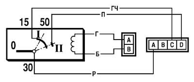
Figure 7-3. Ignition Switch Wiring Diagram (with the key inserted):
Table 7-3. Circuits switched on at different key positions

The locking rod of the anti-theft device must extend when the key is set to position 0 (off) and removed from the lock. The locking rod must retract after turning the key from position 0 (off) to position I (ignition). The key must be removed from the lock only in position 0.
The starter reactivation interlock must prevent the key from being turned again from position I (ignition) to position II (starter). Such a turn must only be possible after the key has first been returned to position 0 (off).
Car anti-theft system (immobilizer) has a special indicator in the control lamp block, which is switched on in the following cases:
- if the APS is not activated, then after the ignition is turned on, the control lamp turns on and remains lit until the ignition is turned on. In this case, you must contact a service station to activate it;
- if the control lamp flashes when the ignition is turned on, then the APS is faulty and you should contact a service station to fix the problem;
- when using the training key (ignition key with a red insert on the end) the indicator lamp flashes for 6 seconds when the ignition is turned off.