


Headlights
The cars use a headlight assembly that combines low-beam and high-beam headlights (with single-filament lamps) and direction indicators. In addition, one of the headlights contains a parking light bulb.
The headlight switching circuit is shown in Figure 7-21. The low and high beam headlights are switched on using auxiliary relays K4 and K5, located in the mounting block. The control voltage is supplied to the relay windings from headlight switch 3 if the switch button 5 for external lighting is fully pressed. When the low beam is switched on, the low beam lamps light up, and when the high beam is switched on, all lamps light up (both low and high beam).
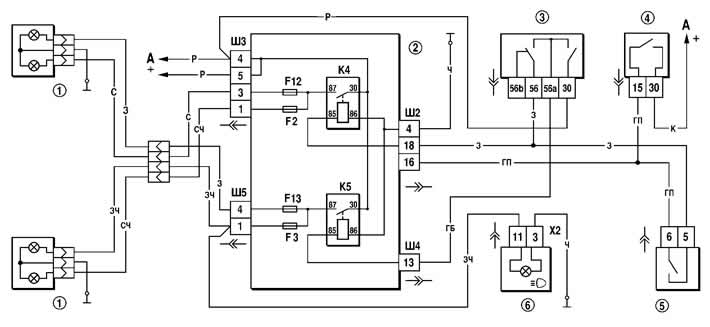
Figure 7-21. Headlight connection diagram:
1 - headlights;
2 - mounting block;
3 - headlight switch;
4 - ignition switch;
5 - outdoor lighting switch;
6 - High beam indicator lamp in the instrument cluster;
K4 - low beam headlight relay;
K5 - high beam headlight relay;
A - to power sources.
Regardless of the position of switch key 5, you can briefly turn on the high beam headlights by pulling the lever of switch 3 of the headlights towards you. In this case, voltage is supplied to contact "30" of switch 3 directly from the power sources.
Fog lights
The fog lamp connection diagram is shown in Figure 7-22. The lamps are switched on by switch 4 using auxiliary relay 5 of type 904.3747-11 or 904.3747-11A, installed in the socket attached to the rear side of the mounting block. The fog lamps can only be switched on if the external lighting is switched on by switch 3.

Figure 7-22. Fog lights wiring diagram:
1 - fog lights;
2 - mounting block;
3 - outdoor lighting switch;
4 - fog light switch;
5 - fog light relay;
A - to power sources.
Fog light
The fog light switching circuit is shown in Figure 7-23. Fog light lamps 3 in the rear lights are switched on by switch 4 via the APS control unit 5 only if the headlights are on (the corresponding switch key 2 of the external lighting is fully pressed). When the parking lights are turned off, the rear fog lights are turned off automatically.
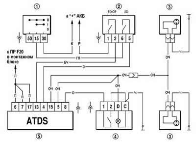
Figure 7-23. Fog lights wiring diagram:
1 - ignition switch;
2 - outdoor lighting switch;
3 - fog lamps in the rear lights;
4 - rear fog light switch;
5 - control unit of the car anti-theft system.
Outdoor lighting
The diagram for switching on the external lighting is shown in Figure 7-24. The side light is switched on by external lighting switch 6.
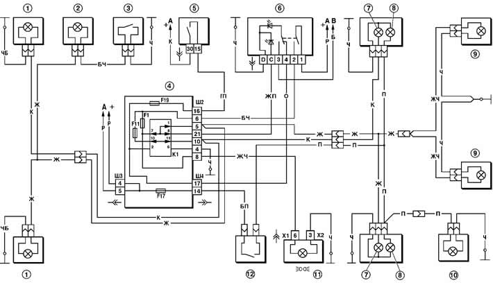
Figure 7-24. Outdoor lighting connection diagram:
1 - side light bulbs in headlights;
2 - underhood lamp;
3 - underhood lamp switch;
4 - mounting block;
5 - ignition switch;
6 - External lighting switch;
7 - side light bulbs in the rear lights;
8 - brake light bulbs in the rear lights;
9 - additional brake signal;
10 - License plate lights;
11 - External light indicator lamp in instrument cluster;
12 - brake light switch;
K1 - lamp health control relay (inside the relay are shown contact jumpers that must be installed if there is no relay);
A - to power sources;
B - to the instrument lighting lamps.
The parking light and brake light lamps are powered via the K1 lamp health monitoring relay. If the lamp health monitoring relay is not installed in the mounting block, then the contact jumpers shown by the arrows in Figure 7-24 should be installed instead.
Direction indicators
The diagram for switching on the direction indicators and hazard warning lights is shown in Figure 7-25. The direction indicators for the right or left side are switched on by switch 3. In the hazard warning mode, switch 6 switches on all direction indicators. Flashing of the lamps is provided by relay-breaker K3 in the mounting block.
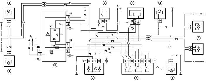
Figure 7-25. Direction indicator and hazard warning light connection diagram:
1 - direction indicator lamps in headlights;
2 - ignition switch;
3 - direction indicator switch;
4 - side direction indicators;
5 - direction indicator lamps in the rear lights;
6 - hazard warning switch;
7 - instrument cluster with direction indicator and hazard warning lights;
8 - mounting block;
K3 - relay-interrupter of direction indicators and hazard warning lights;
A - to power sources.
(For details, visit the website «chevyman.ru»)