


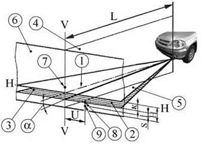
Figure 7-28. Adjusting the fog lights on the screen:
1 - reference axis of the light device (headlight);
2 - horizontal (left) part of the light and shadow border;
3 - inclined (right) part of the light-shadow border;
4 - vertical plane passing through the reference axis;
5 - a plane parallel to the plane of the working platform on which the vehicle is installed;
6 - screen plane;
7 - position of the control point for measuring the luminous intensity of the fog lights in the 3° upward direction;
8, 9 - coordinates of points for measuring the position of the light-shadow boundary in the vertical plane;
"K" - the distance on the screen from the projection of the optical center of the headlight to the position of the cut-off line of the light beam of the fog light (200 mm);
"H" - the distance from the projection of the optical center of the headlight to the plane of the working platform;
"U", "S" - coordinates of the measurement points of the cut-off line position in the horizontal and vertical planes, respectively ("U" values < 600 mm; "S" = 174.5 mm).
Place a fully fueled and equipped vehicle, with a load of 735 N (75 kgf) on the driver's seat, on a level horizontal surface 10 m from the screen (a shield measuring about 2x1 m, etc.) so that the car's axis is perpendicular to it. Before marking the screen, make sure that the air pressure in the tires is 0.19 MPa (1.9 kgf/cm²), and then squeeze the car suspension 2-3 times to adjust its components.
Check and, if necessary, adjust the direction of the light of the fog lights. In this case, the upper light-shadow boundary of the fog light beam should be parallel to the plane of the work platform on which the vehicle is installed.
The headlights are adjusted by turning screw 1 (figure 7-29), which rotates the optical element in the horizontal plane.
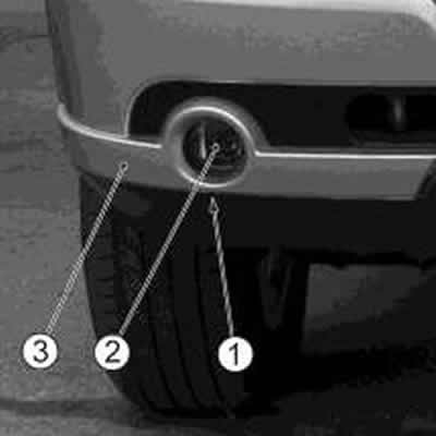
Figure 7-29. Adjusting the fog light:
1 - location of the adjusting screw;
2 - fog light;
3 - front bumper.
The luminous intensity of the fog lamps, measured in the vertical plane passing through the reference axis, must be no more than 625 cd in the direction 3° upward from the position of the cut-off line. If the luminous intensity does not correspond to the value specified above, perform a repeat adjustment of no less than 0.5% in the vertical direction from the angle of 69' and measure the luminous intensity.