


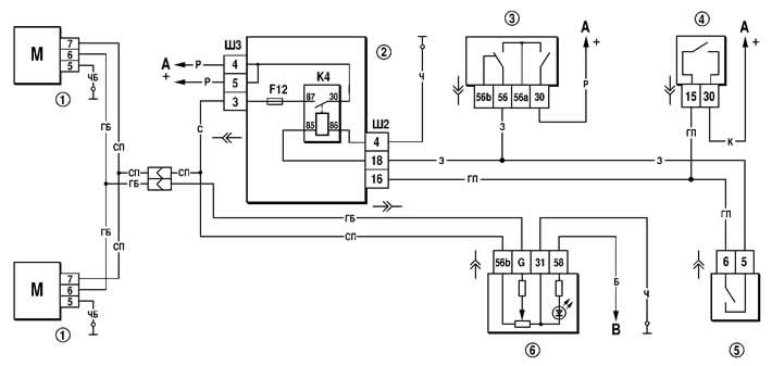
Figure 7-35. Wiring diagram for headlight correctors:
1 - headlight corrector motor reducer;
2 - mounting block;
3 - headlight switch;
4 - ignition switch;
5 - External lighting switch;
6 - headlight correction regulator;
K4 - low beam headlight relay;
A - to power sources;
B - to the instrument lighting controller.