


- Nominal shaft speed when the electric motor is loaded with an impeller, min⁻¹ — 2600-2800
- Current consumption at the specified load and rotation speed, A, no more than - 25
To drive the fans of the engine cooling system, two domestically produced DC electric motors with excitation from permanent magnets are installed.
The electric motors are switched on by the engine management system controller, Figure 7-37, through auxiliary relays and fuses, individually or in pairs.
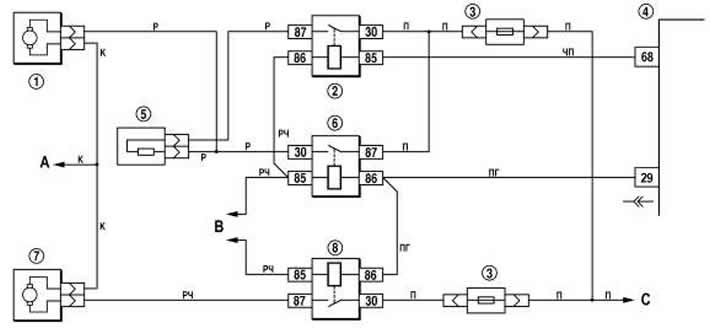
Figure 7-37. Wiring diagram for the cooling system fan motors:
1 - right electric motor of the engine cooling system fan;
2 - additional relay;
3 - fuse;
4 - controller;
5 - additional resistor;
6 - relay for switching on the right electric motor;
7 - left electric motor of the engine cooling system fan;
8 - relay for switching on the left electric motor;
A - to the "-" terminal of the battery;
B - to the ignition relay;
C - to the "+" terminal of the battery.
Electric motors do not require maintenance and should be replaced with new ones in case of failure.